555 Optical Theremin
Two photocells on a 555 astable, with a real note-off · By Onion Madder · Mess O' Pedals
A two-handed light theremin from one 555 and a pair of photocells. The cells sit in series as the timing resistor, so either hand moves the pitch on its own and both together move it further: roughly 1 kHz in room light, down through the bass as you shade them. Cup both and it stops dead rather than sliding into a fart, and that note-off is the part that makes it playable. Everything pushes into a breadboard, there is no soldering at all, and it drives a speaker directly with no amp.
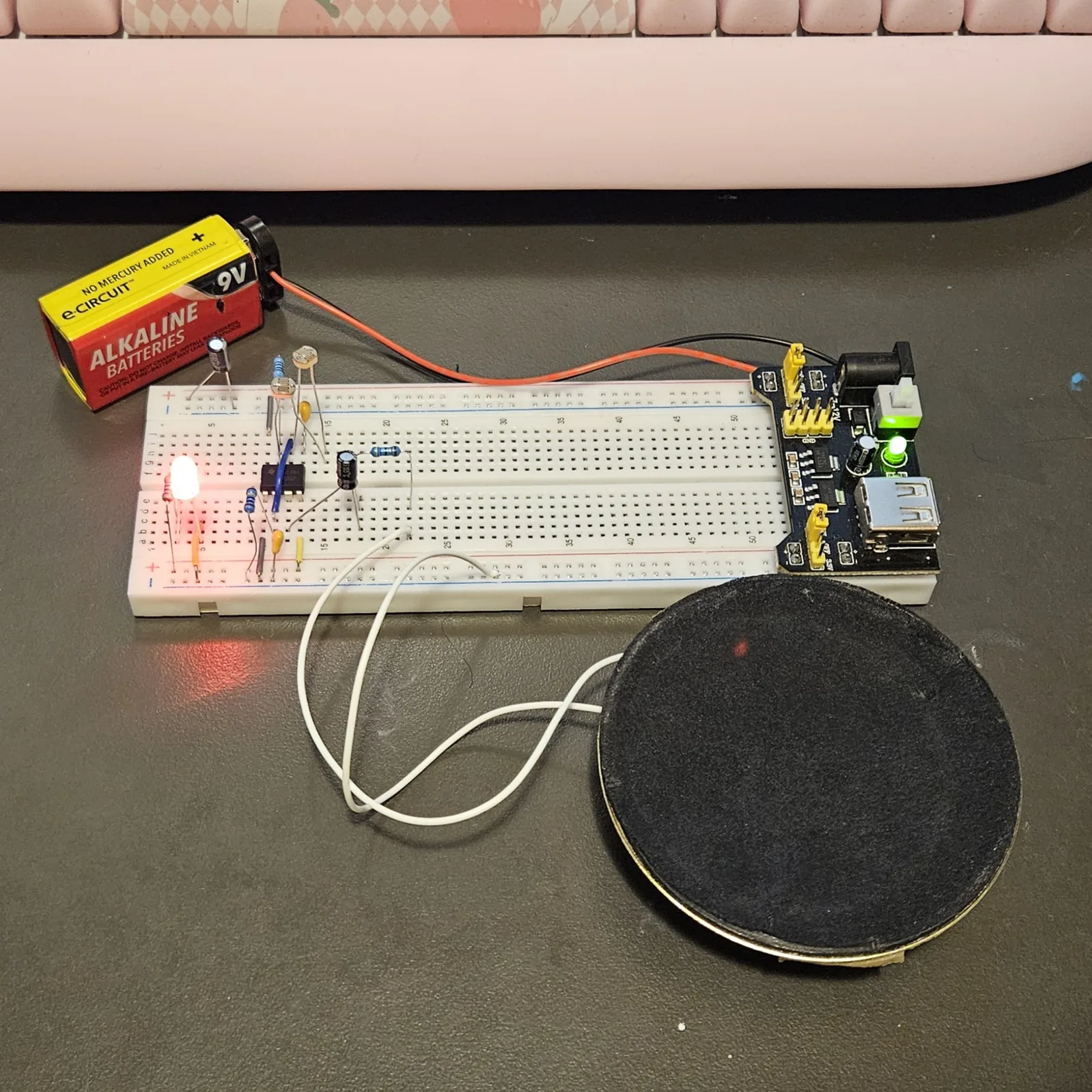
This is the second theremin in the breadboard series. The Optical Theremin does the job with a CD40106 and gets you six voices on one chip; this one is a single voice on the most common chip in the drawer, it drives a speaker directly, and it is the only build here that can actually be silenced. If you have built the Atari Punk Console you have already wired a 555 astable, because that is the half of it that makes the pitch. Power is a 9V battery into a breadboard power module set to 5V, which is what the photos show.
⚠ Before you start tap to expand / collapse
No iron needed. Every part in this build pushes into the breadboard, including the mod.
Mind polarity on both 100 µF electrolytics. The stripe down the can marks the minus leg, and the longer leg is plus. Backwards is the one mistake here that can damage a part rather than just stay quiet.
The 10K in step 6 is not optional. It is what stops the chip's discharge pin from being tied straight to the supply when the photocells are in bright light. Leave it out and you are asking pin 7 to sink the rail.
The 1M in step 9 is what makes it an instrument. Leave it out and the build still works, but the low end just sags into a slow fart instead of stopping.
This build uses both pairs of rails. The power module plugs into the top and the bottom rail pairs at the right-hand end, so plus and minus are live along both edges of the board.
What you'll need
tap to expand / collapse
New to the parts? Each line notes how to spot it - the printed marking, the package, or the polarity clue.
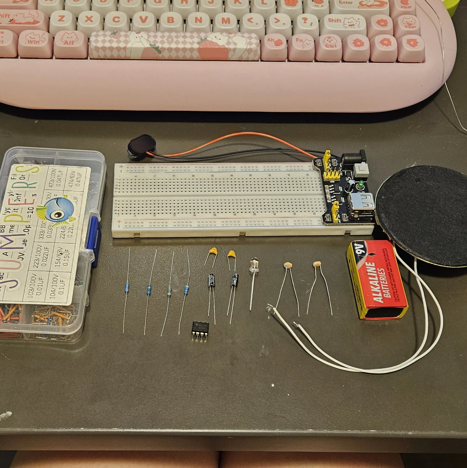
- 1× NE555 timer, 8-pin DIP - spot it: 555 in the part number printed on top; a notch in one end, and a dot beside pin 1
- 2× LDR photocell (GL5528 or similar) - spot it: the little disc with the wavy orange trace across its face. These are your two hands on the instrument.
- 1× 10K resistor - the fixed half of the timing pair, and what sets the top of the range. Spot it: bands brown-black-orange-gold.
- 1× 1M resistor - the note-off. Spot it: bands brown-black-green-gold.
- 1× 47 ohm resistor - in series with the speaker. Spot it: bands yellow-violet-black-gold.
- 1× 0.01 µF ceramic - steadies the control pin. Spot it: printed 103.
- 1× 0.1 µF ceramic - the timing cap, and what sets the range. Spot it: printed 104.
- 2× 100 µF electrolytic - one couples the speaker, one steadies the supply. Spot it: a little can; the stripe marks the minus leg, longer leg is plus.
- 1× small speaker - anything from 8 to 32 ohms.
- 4× jumper wire - three for power and reset, one long one to tie two pins together across the channel.
- Breadboard, a power module set to 5V, and a 9V battery to feed it.
- For the mod (power LED): 1× LED, 1× 470 ohm resistor and one more jumper - spot it: the LED's long leg is plus and the short leg sits behind the flat spot on the rim; the 470 reads yellow-violet-brown.
Reading the breadboard
This guide names exact holes, like E10 or H11. Letters run across the board and numbers run along it, and both are printed on the board itself, so every instruction below points at one hole you can put a finger on.
The center channel splits the letters into two banks: A to E on one side and F to J on the other, with E and F being the two rows either side of the channel. The five holes in a bank that share a number are all the same electrical point. So A10, B10, C10, D10 and E10 are one node with five ways in, which is why step 1 puts a chip pin in E10 and step 2 then runs a jumper from A10: same node, different hole, and the chip pin is not in the way.
Turn the board so the numbers climb left to right and the power module is on your right, as in the photos. Then the top rails are the pair above the F to J bank and the bottom rails are the pair below A to E, and the module feeds both.
Quick reference - the whole build on one card
The pinout with the hole each pin lands in, plus every connection at a glance. The steps below walk through it slowly; this is the bench card.
The notch points left. Pin 1 goes in E10 and pin 8 lands in F10 directly across the channel - then every other pin falls on the hole shown. Anywhere in the same bank and column is the same point, so F11 and H11 are both “pin 7”.
Power (first)
- A10 → bottom − rail (pin 1, ground)
- J10 → top + rail (pin 8, 5V)
- A13 → bottom + rail (pin 4, reset held high)
- 0.01µF: H13 → top − rail (pin 5)
The oscillator
- 10K: top + rail → H11 (into pin 7)
- LDR 1: G11 → G15
- LDR 2: H15 → H12 - the two cells are in series
- Jumper: I12 → C11 (pin 6 to pin 2)
- 0.1µF: B11 → bottom − rail
- 1M: A11 → bottom − rail (the note-off)
Out to the speaker
- 100µF: + leg B12, − leg B18
- 47 ohm: D18 → D22
- Speaker: A22 and the bottom − rail
Supply
- 100µF near column 5: + leg top + rail, − leg top − rail
- Both electrolytics are polarised. Stripe is minus.
Steps 1–5 The chip and its jumpers
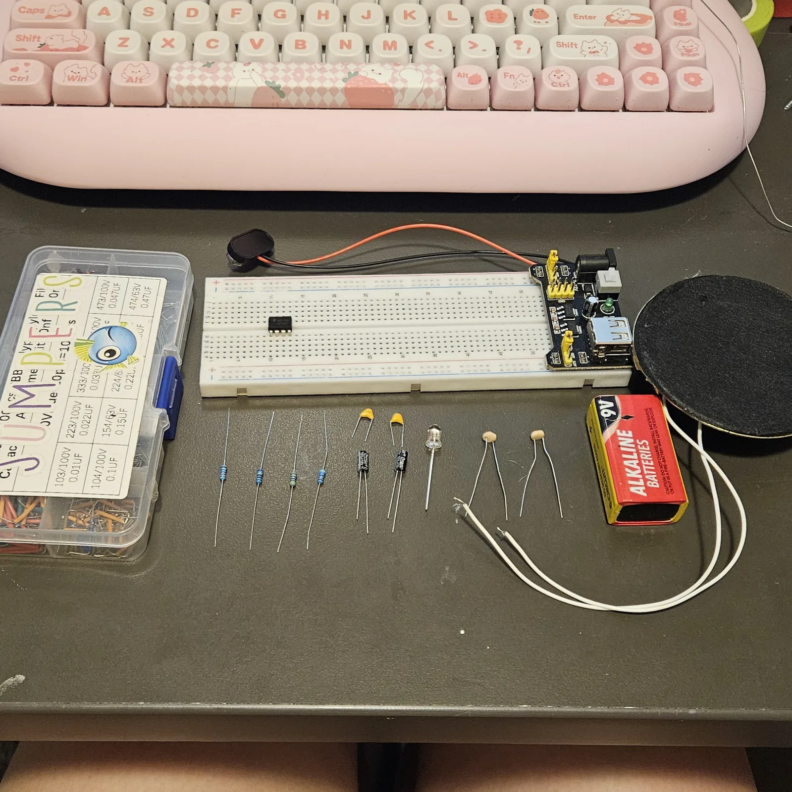
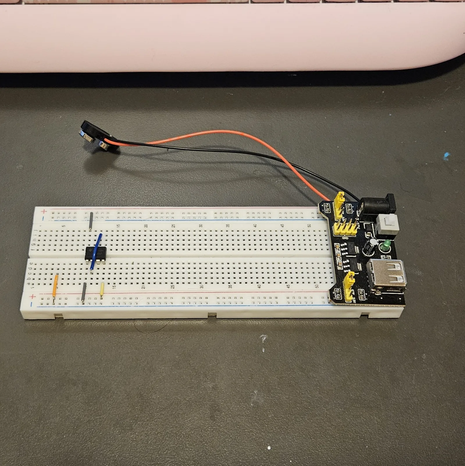
The notch is at one end of the chip and there is a dot next to pin 1. Everything in this guide assumes the notch points left and pin 1 lands in E10 - put the chip anywhere else and every hole below shifts with it. Then all four jumpers go in together, including the long one that crosses the channel.
| Step | Do |
|---|---|
| 1 | Seat the 555 across the center channel, notch to the left: pin 1 in E10, pin 4 in E13, pin 5 in F13, pin 8 in F10 |
| 2 | Jumper: A10 to the bottom − rail (pin 1 to ground) |
| 3 | Jumper: J10 to the top + rail (pin 8 to 5V) |
| 4 | Jumper: A13 to the bottom + rail (pin 4, reset, held high) |
| 5 | Jumper: I12 to C11 (pin 6 to pin 2) |
Step 4 is the one people skip. The 555's reset pin is active low: left floating it can sit low enough to hold the chip switched off, and you get silence with nothing visibly wrong. Tie it to plus and it stays awake.
Step 5 crosses the channel, so it is the one jumper that has to be long. Pins 6 and 2 sit on opposite banks and opposite columns, and joining them is what makes the chip retrigger itself the instant the cap empties.
Steps 6–10 The resistors and photocells
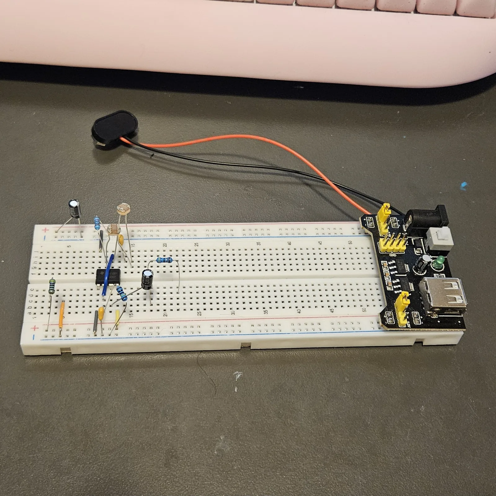
Everything that resists, in one pass: the 10K that feeds the discharge pin, the two photocells that are the instrument, the 1M that gives you the note-off, and the 47 ohm that sits in front of the speaker.
| Step | Do |
|---|---|
| 6 | Resistor 10K: top + rail to H11 (5V into pin 7) |
| 7 | LDR 1: one leg in G11, the other in G15 (off pin 7) |
| 8 | LDR 2: one leg in H15, the other in H12 (chain lands on pin 6) |
| 9 | Resistor 1M: A11 to the bottom − rail (the note-off) |
| 10 | Resistor 47 ohm: D18 to D22 |
The cells go in series, not side by side. Shading either one adds resistance to the same chain, so each hand works on its own and the two stack.
What the 1M actually does. It sits from the timing node to ground, so it forms a divider with the 10K and the photocells above it. Once the two cells together pass roughly 490k, the cap can no longer be charged to two thirds of the supply, the threshold is never reached, and the chip simply stops. That is your note-off: cup both cells and it goes silent, open your hands and it comes straight back. The threshold is a ratio, not a voltage, so it lands in the same place on 5V or 9V.
Steps 11–14 The capacitors
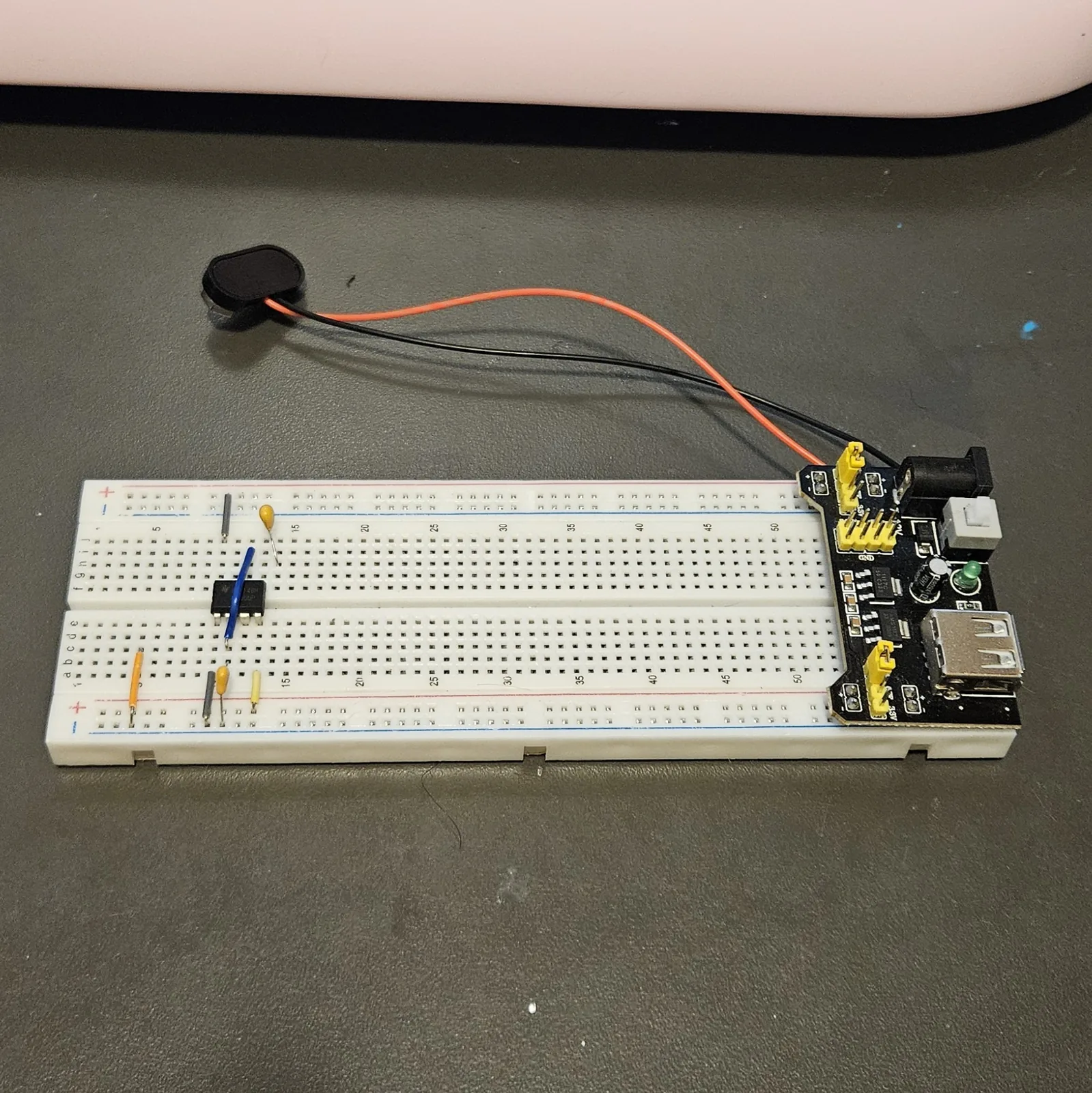
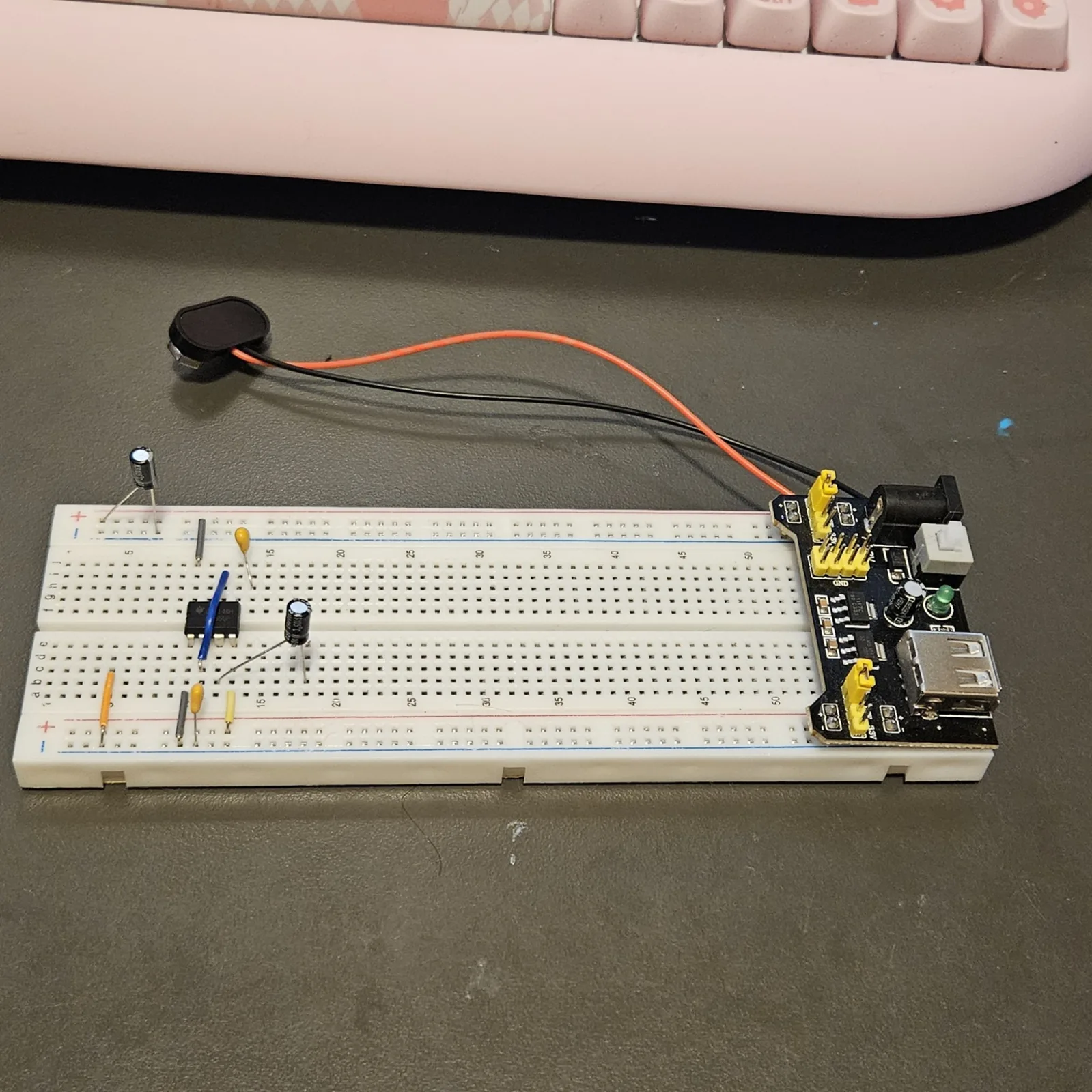
Two ceramics and two electrolytics. The ceramics steady the control pin and set the range; the electrolytics keep the speaker's DC out of your ears and hold the supply still while the speaker pulls at it.
| Step | Do |
|---|---|
| 11 | Cap 0.01 µF (103): H13 to the top − rail (pin 5) |
| 12 | Cap 0.1 µF (104): B11 to the bottom − rail (the timing cap) |
| 13 | Cap 100 µF: + leg into B12, − leg into B18 (coupling, off pin 3) |
| 14 | Cap 100 µF near column 5: + leg into the top + rail, − leg into the top − rail |
Both caps in steps 13 and 14 are polarised and both are 100 µF, so it is easy to fit one the wrong way around while concentrating on the other. The stripe down the side of the can marks the minus leg.
Steps 15–16 Speaker, and power up
The speaker is the only thing here that is not on the board. Its two leads go straight in, which is why this build needs no amp.
| Step | Do |
|---|---|
| 15 | Speaker: one lead into A22, the other into the bottom − rail |
| 16 | Flip the module's power switch on. Its green LED should light. |
Then wave both hands over the cells. Shade one and the pitch drops; shade both and it drops further; cover both properly and it cuts out. A phone flashlight gives far more range than shadow alone, and a much steadier hand.
⚠ If it doesn't work
| Symptom | Check |
|---|---|
| Nothing at all, module LED lit | Steps 2, 3 and 4. A missing reset jumper looks exactly like a dead circuit. |
| Nothing at all, module LED dark | The battery, the module's switch, and that the module is set to 5V rather than 3.3V. Both jumper blocks, not just one. |
| Still nothing, everything looks right | Probe pin 3 - any free hole in column 12, lower bank. A working build twitches around 2 to 3V DC average there. If pin 3 is moving, the fault is after it: the coupling cap, the 47 ohm, or the speaker. |
| Silent, but every reading looks healthy | The ceramics are swapped. 104 is the timing cap in step 12, 103 is the bypass in step 11. Backwards it oscillates near 48kHz - perfectly alive, entirely inaudible. |
| Sound, but the light does nothing | The photocell chain and the long jumper. Either the two cells are not bridging pins 7 and 6, or threshold is not tied back to trigger. |
| It never cuts out, just sags | Step 9. The 1M is missing or in the wrong column - it belongs at A11, sharing pin 2's strip. |
| It cuts out at the slightest shade | The 1M is actually a smaller value, or one photocell is much darker than the other. Swap the 1M up to 2.2M if you want to work harder for the silence. |
| Very quiet | Take the 47 ohm out entirely and let the 555 drive the speaker directly - it will take 200mA all day. |
| Pitch far too high everywhere | Too much light on the cells, or the 0.1 µF in step 12 is actually the 0.01 (check for 104, not 103). |
| A thud on power-up, then silence | One of the electrolytics is in backwards. Stripe is minus. |
Mod: a power LED
Do this after the basic build works. The module has its own green LED, but it only tells you the module is awake. This one tells you the rail your circuit is actually sitting on is live, which is the more useful thing to know.
Mod Power LED
| Step | Do |
|---|---|
| 1 | Resistor 470 ohm: bottom + rail to C3 |
| 2 | LED: long leg (anode) into A3, short leg into A5 |
| 3 | Jumper: C5 to the bottom − rail |
That runs about 6mA at 5V with a red LED - plenty indoors, and nowhere near enough to rob the 555. Want it brighter? Drop to 220 ohm for around 14mA. Blue and white LEDs have roughly a 3V forward drop, so at 5V use 220 ohm with those or they will look dim.
How it works, in one breath
A 555 wired as an astable charges a capacitor up through a resistance and discharges it down again, over and over, and the speed of that is the pitch. Here the fixed part is the 10K and the variable part is two photocells in series, so both hands work on the same chain: shade either one and you add resistance to it, shade both and you add more. In room light that lands around 1 kHz, and it walks down into the bass as the light goes.
What the 1M actually does. It sits from the timing node to ground, so it forms a divider with the 10K and the photocells above it. Once the two cells together pass roughly 490k, the cap can no longer be charged to two thirds of the supply, the threshold is never reached, and the chip simply stops. That is your note-off: cup both cells and it goes silent, open your hands and it comes straight back. The threshold is a ratio, not a voltage, so it lands in the same place on 5V or 9V.
Everything else on the board is housekeeping: reset tied high so the chip stays awake, a small cap steadying the control pin, a big cap keeping the speaker's DC out of your ears, and another one holding the supply still while the speaker pulls at it.
Things to try
- Spread the cells out. At columns 11 and 15 they are only four tenths of an inch apart, which is a pinch rather than a gesture. Jumper G11 to G30, put LDR 1 across G30/G34 and LDR 2 across H34/H38, then jumper I38 back to H12. Same circuit, arm's-length playing.
- Swap the timing cap. 1 µF in place of the 0.1 drops the whole thing below hearing into a slow click you can watch. 0.01 µF sends it up into a whistle.
- Move the 1M and you move the note-off. 470k cuts out with barely any shade; 2.2M makes you nearly seal both cells off. It is the only knob on this build that changes how it feels to play rather than how it sounds.
- Play it with a flashlight, not a shadow. You get the full range instead of the top half of it, and far more control.
- Put one cell in a tube. A short cardboard sleeve narrows what the light can reach, which turns a vague wave into something you can aim - and leaving the other cell open gives you one coarse hand and one fine one.
- Shrink the 10K and the bright end climbs further; grow it and the whole range moves down. It is the floor the photocells sit on.
- Don't bother flashing an LED with the note. Tying an LED to pin 3 so it blinks in time is the obvious idea and it does not work: at audio rates it just looks like a steady dim glow. Real visual feedback needs a second slow 555, or an RC lowpass off the output driving a transistor - a whole separate block, and a fun one if you want to go there later.
- Then solder one. The same oscillator, built to keep, is the Dead-Bug Mosquito.
The 555 astable is folk knowledge, and the light-controlled version of it has been passed around hobby electronics since Forrest Mims was drawing them by hand. The nudge to build one at all came from Battle of the Bands: 555 Timer Edition by Michael D'Argenio, an engineer turned educator who runs it as a classroom activity: a theremin, an organ and an Atari Punk Console, all out of 555s. He credits Mims for the stepped tone generator too, which is the same circuit as the Atari Punk Console in this series. His site is worth an afternoon. The second cell and the 1M note-off are my own addition, and they are what turn it from a demo into something you can play. This breadboard recipe, the hole-by-hole wiring and the words are mine, built and measured on the bench. Build it, bend it, make it yours.