Simple Ring Modulator
Four diodes and two transformers, drawn in Copper Bottom and built · By Onion Madder · Mess O' Pedals
A ring modulator multiplies two signals together and gives you the sum and the difference, with neither of the originals getting through. It is the sound of the Daleks, of a bell that is not quite a bell, of a synth turning into a machine. The classic circuit is passive: four diodes in a ring between two transformers, and not a volt of supply anywhere. No chip, no battery, no power pads. Feed it two things and it works - as long as the two things are loud enough, which is the part this page is honest about further down.
What you'll need
tap to expand / collapse
- 4× 1N4148 diode - spot it: a small glass body with a black band at one end, and that band is the cathode. All four go in the ring, and their direction is the circuit: two point one way, two the other. Get one backwards and you have a rectifier instead of a modulator
- 2× audio transformer, 600 Ω center-tapped to 600 Ω, five pins - the little EI14 ones sold by the bag on AliExpress for less than a coffee. Spot it: a cream bobbin about 14 by 10 mm with a yellow-taped core, three pins on one side and two on the other. The three-pin side is the tapped winding and the middle pin is the tap. The layout is drawn around this exact part: the three pins land one hole apart, the two pins two holes apart, and the two rows sit four columns apart. That is the spacing my parts went into, so it fits - but seat both transformers in their holes before you solder anything else, because the row spacing is the one dimension a bag from a different seller could change. The first drawing of this board was around a Triad TY-141P, and the part every other write-up recommends is the Xicon 42TM022; either works in the circuit, but their pins land in different holes, so redraw in Copper Bottom before you cut for one of those
- 3× 2u2 film capacitor - the coupling caps. No polarity, so they cannot go in backwards. They keep any DC on your inputs and outputs out of the transformers
- 1× stripboard, 9 strips × 25 holes or larger
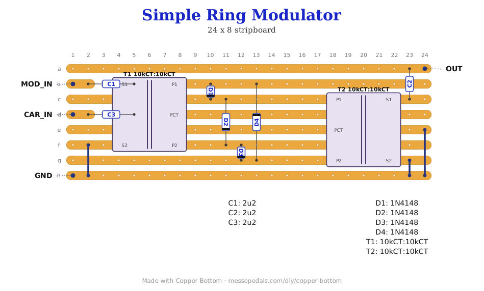
- Five wire links and hookup wire for the four off-board leads. Three links carry T1's outer winding end, T2's center tap and T2's outer winding end down to the ground strip; the other two are one hole long and join the two halves of a ring node either side of T2's pins
- Eight track cuts. A pair under each transformer splits the strips between its two windings, a pair sits under D1 and D3 so each diode bridges its own cut, and two on the center strip keep the middle of the ring away from the two taps
Off the board
- 3× 1/4″ mono jacks - two inputs and the output. It is passive, so that is the whole panel
- 1× 125B enclosure, if you box it - mine is the pink one further down the page
The layout file is the guide
Like the 555 theremin and the Opto Duet, the build document here is the file itself: ↓ Download Simple_Ring_Modulator.json
Open Copper Bottom and import it. The board is 9 strips of 25 holes, with 8 track cuts, 5 links and 14 parts, and it is the file I built from, not a tidied-up copy. The editor draws it, walks you through placing it in a sensible order, checks the copper against the netlist, and prints the whole thing at 1:1 for the bench. None of those coordinates are typed out on this page on purpose: the file is the one copy, so there is nothing here to fall out of step with it.
The netlist
This is the netlist embedded in the file, verbatim. It was written from the drawn board, so checking that board against it can only agree with itself. What it is good for is carrying the circuit somewhere else, and giving your meter something to walk when you are hunting for why it is silent:
The off-board wiring
Four pads leave the board, and there is no supply among them:
| Pad | Goes to |
|---|---|
| CAR IN | The carrier, usually the higher and duller of the two: an oscillator, a square wave, one of the theremins on this shelf. It goes through C2 to T1's center tap and nowhere else, which is the whole trick - it reaches the diode ring only through that tap |
| MOD IN | The program input, the one you care about hearing: a synth, a drum machine, a keyboard. Through C1 into T1's untapped winding. Not a guitar straight in - see the next section |
| OUT | The output, taken through C3. It is a passive circuit, so this is quieter than what you put in and it wants a high-impedance input after it. An amp, a pedal, a buffer - not a pair of headphones |
| GND | Ground, shared by both inputs and the output. Everything that is not a signal ends up here |
Built, and what it will and will not hear
It came up first time and it does exactly what the lede promises - with the right thing plugged into it. Three things I found on the bench, in the order they matter:
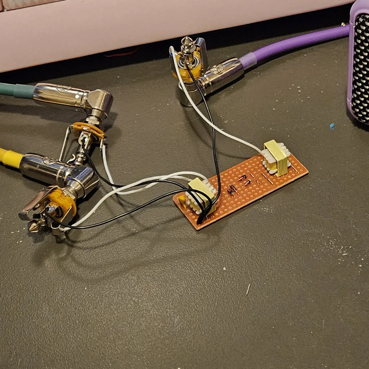
- My home-made synths, it picks up incredibly well. The Cicada NAND, the theremins, the Opto Duet - anything on this shelf into either input and the ring does its thing loudly and cleanly.
- My circuit-bent toys come through, but very quiet. You can hear it working; you have to turn the amp up to hear it working.
- A guitar straight in, it will not hear at all. Silence. Not quiet: nothing.
Those three are observations, and here is what I think is going on, which is not measured and which you should read as a theory. A passive ring has no gain anywhere and two things working against a small signal. The diodes have to be pushed past their forward voltage before they switch at all, about 0.6 V for a 1N4148, and the windings are 600 Ω, which is a heavy load to hang on a source. A synth output swings volts from a low impedance and does not care. A toy's output is a few hundred millivolts and notices. A passive guitar pickup is around a tenth of a volt from a high impedance, so the winding drags it down to almost nothing and the diodes never open. The guitar is not too quiet for the ring; the ring is a short circuit as far as the guitar can tell.
The obvious fix that follows from that is a clean boost or a buffer in front of the program input, and I tried it: it did nothing. The Clean Boost, a one-transistor LPB-1 with about 18 dB in hand, went in front of MOD IN and a guitar still did not get through, so the problem is not level, and the theory above is at best half the story. Germanium diodes in the ring, which switch at a third of the voltage, are the next thing to try and are still untested. If you try them, tell me what happened.
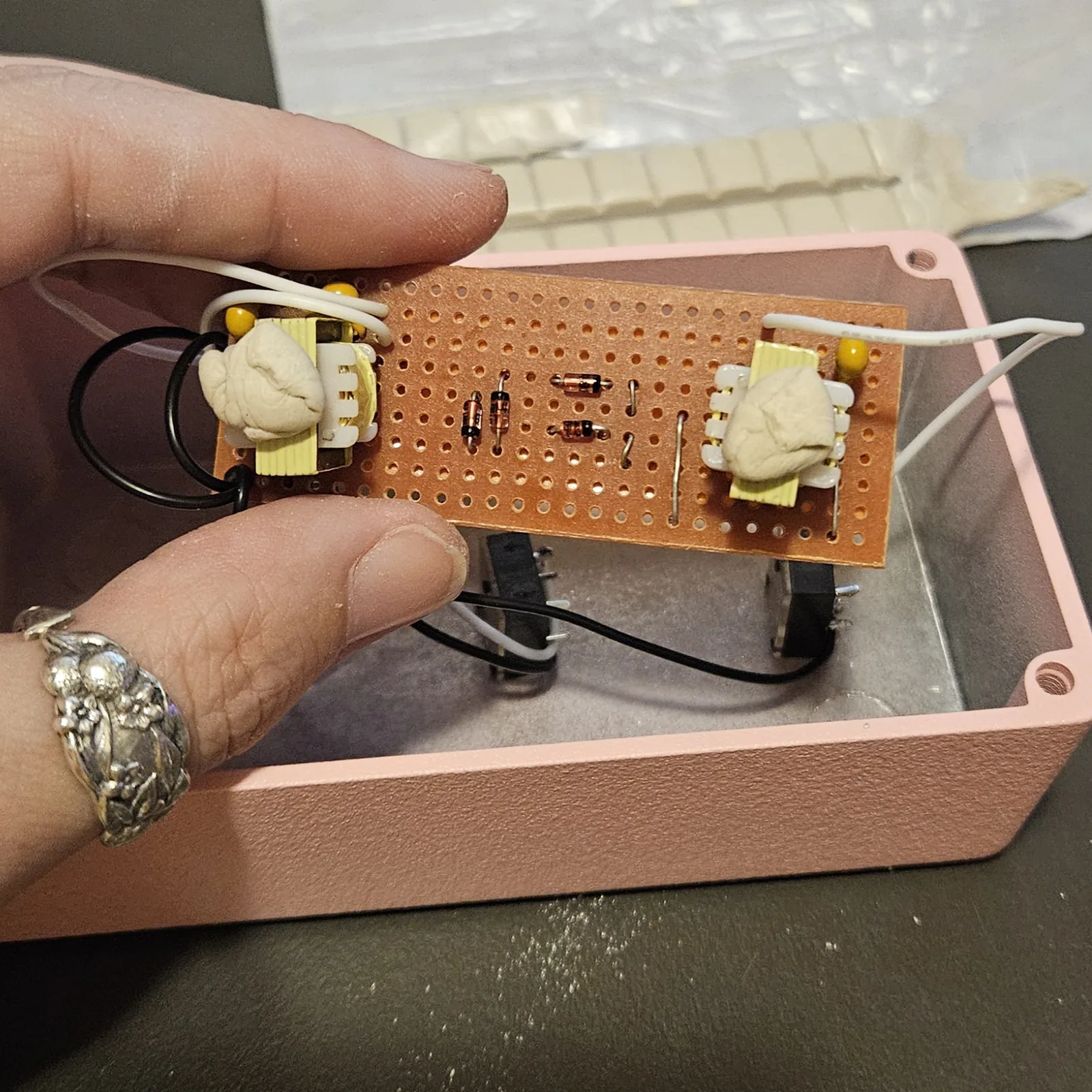
Two things the editor warned about are worth knowing before you build it. C2 sits partly under T1's body in the drawing, and D2 spans only two holes so it stands on end. Both were fine on my board; the diode just adds height, which matters when a lid goes on and not before.
Boxing it up
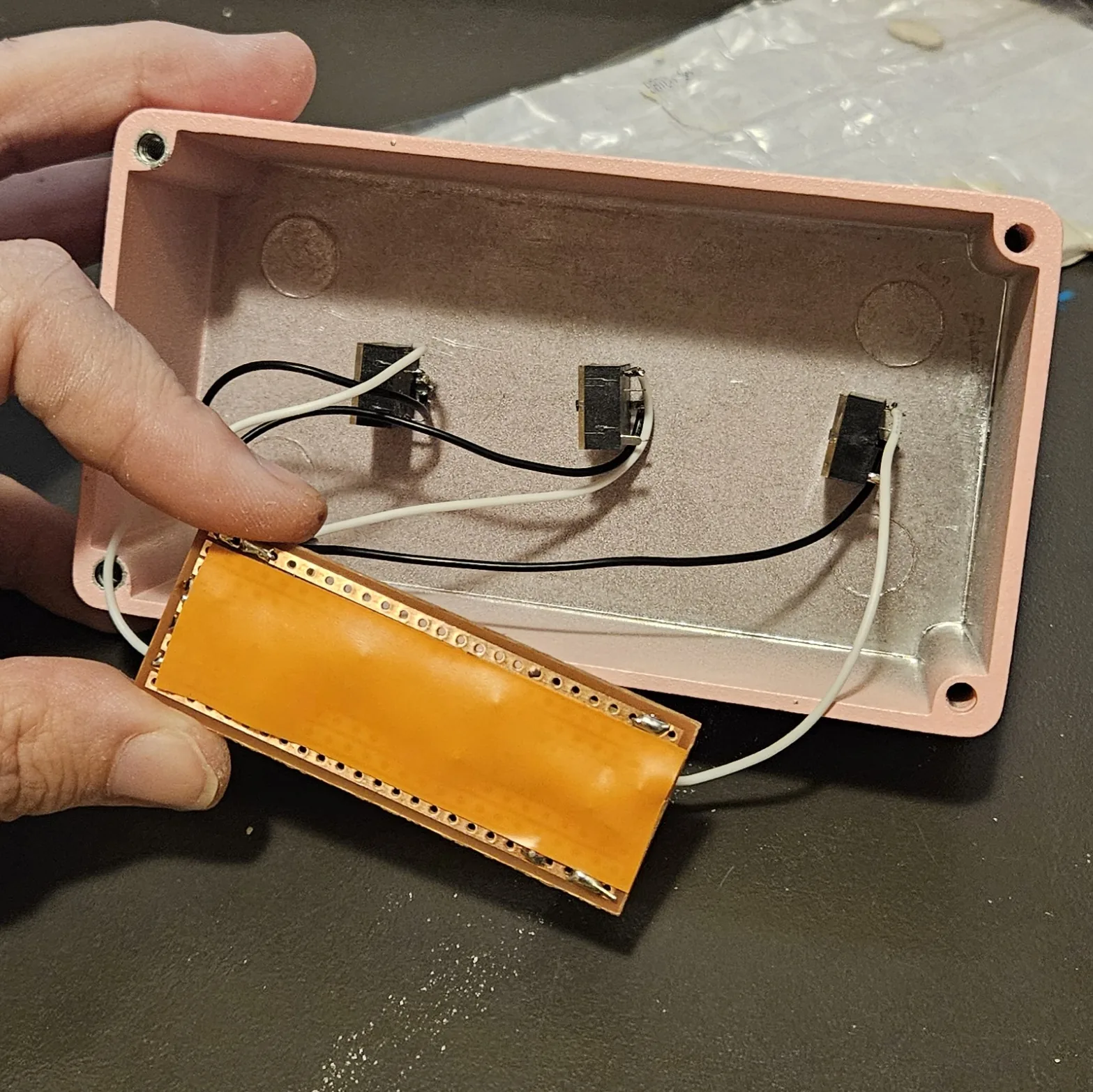
Mine is called Ring-a-Ling and lives in a pink 125B, standing upright, the same format as the rest of this shelf: three jacks in a line down the face and nothing else, because there is nothing else. No supply, no switch, no knob. Three things worth seeing before you do the same.
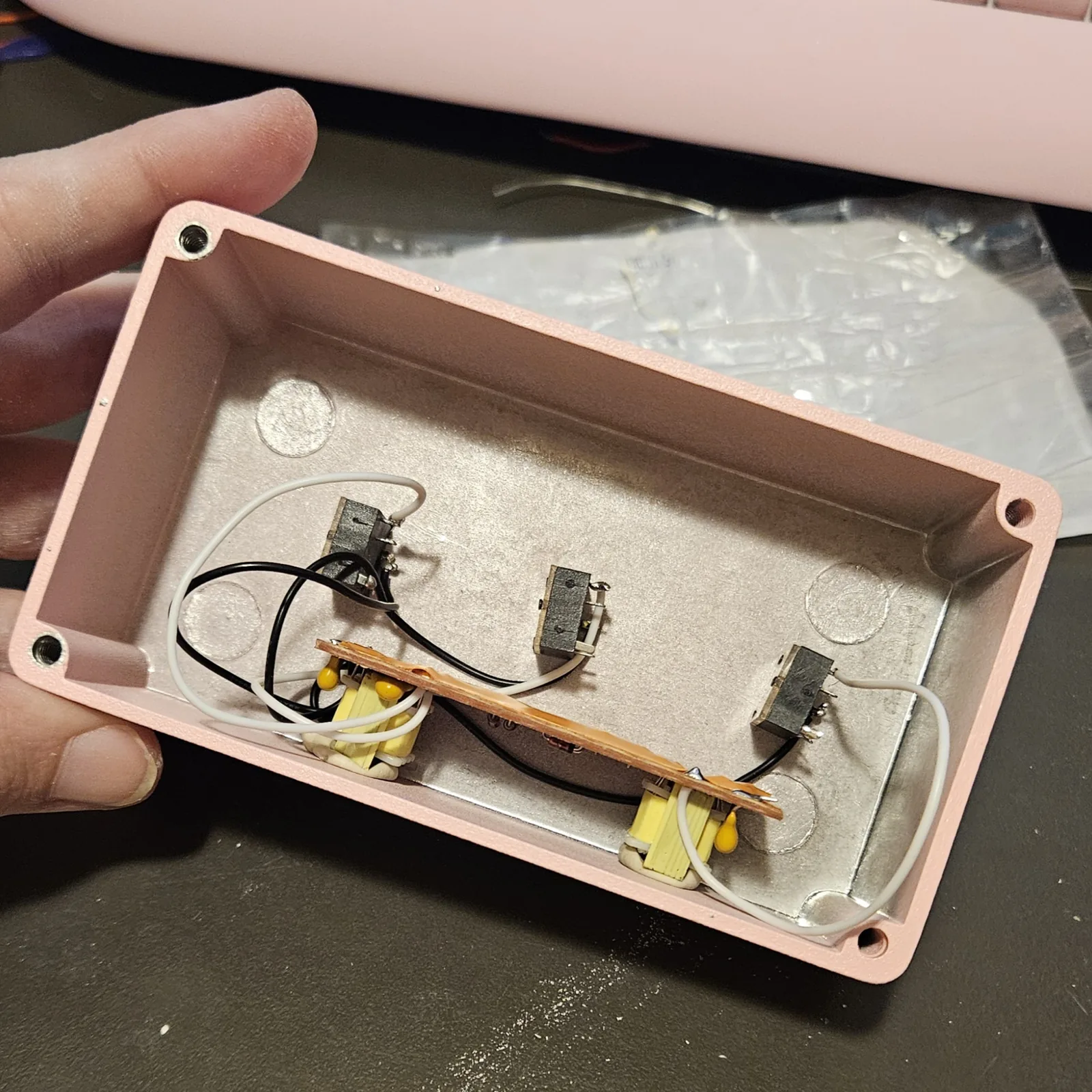
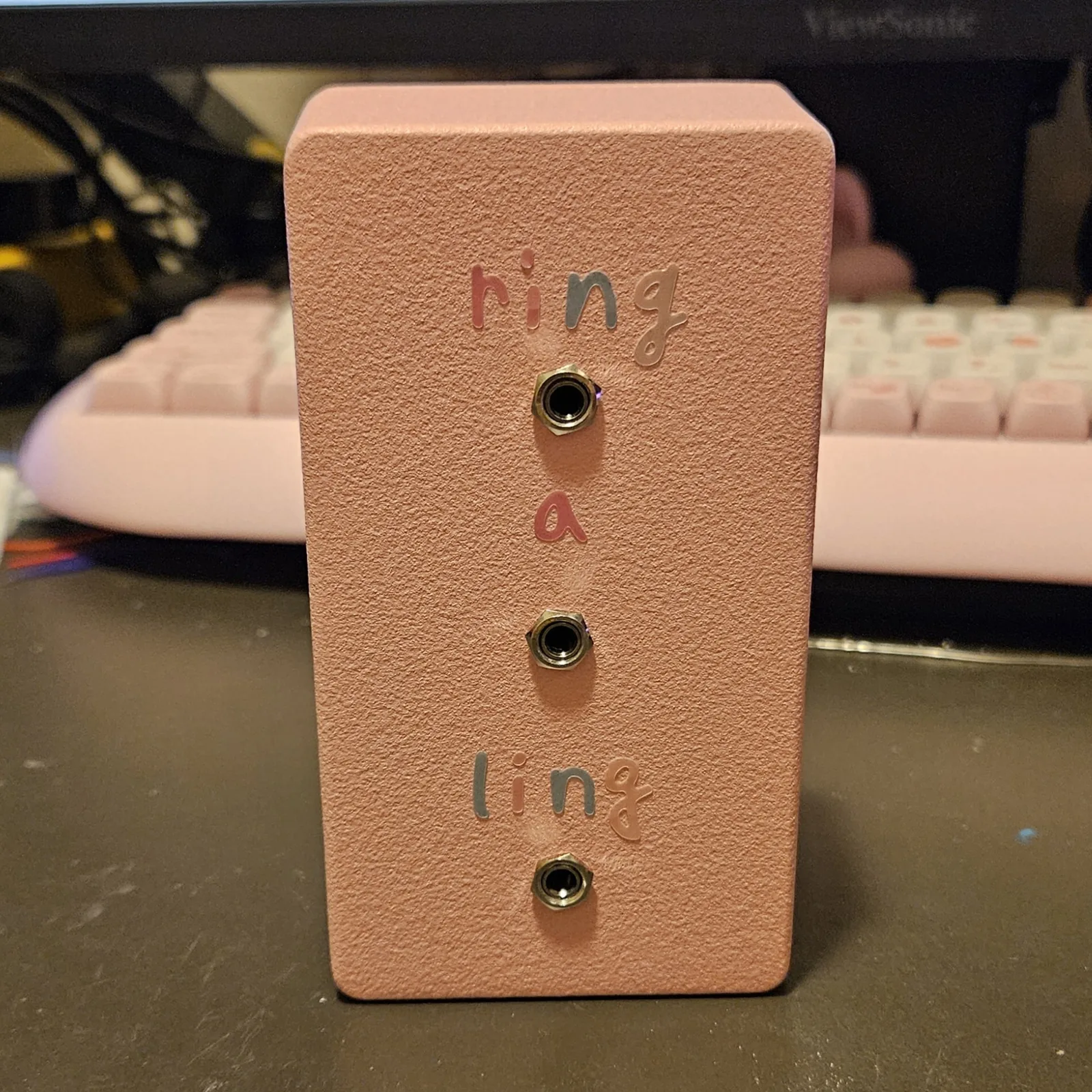
↓ Same box, jacks on top (PDF)
The second sheet moves all three jacks to the top wall and leaves the face blank. Two ways to drill one box; pick one.
Three jacks and nothing else - this circuit is passive, so there is no supply and no DC hole.
Print at 100% / “Actual size”, never “Fit to page” - check the bar measures exactly 4″ before you touch a drill. The face is 66 by 121 mm but only 42 mm of it is drillable once the lid lip is clear.
The pink box above was drilled from this sheet. The hole sizes come from the layout file; where they sit is the house format applied to it. Offer the sheet up to the box and check it against your own jacks before you make a hole.
How it works, in one breath
The program signal comes in on T1's untapped winding and appears across the tapped one, whose two ends are two opposite corners of the diode ring. T2 hangs on the other two corners the same way, and its untapped winding is the output. The carrier does not go through the ring at all: it arrives at T1's center tap, which sits at the electrical middle of that winding, so it pushes both ends the same way at once while the program pushes them in opposite directions.
That is what makes the thing multiply. When the carrier swings one way, one pair of diodes conducts and the program reaches the output one way up; when it swings the other, the other pair conducts and the program arrives inverted. The program gets flipped in step with the carrier, and flipping a signal in step with another is multiplying by it. Out comes the sum and the difference and neither original, because a balanced tap feeds equal and opposite halves that cancel what they have in common.
That is the principle, and the bench agrees with it: feed this board a synth and a carrier and out come the sum and the difference, and neither of the things you put in.
Things to try
- Feed the carrier from a 555 theremin and wave at it while you play through the program input
- Swap which input is which. There is nothing sacred about the labels, and the two sides sound different because the transformers see different things
- Put a volume pot on the carrier. Backing it off takes you from full ring modulation toward the dry signal, which is the tremolo end of the same circuit
- Try germanium diodes in the ring instead of the 1N4148s. Lower forward voltage, so quieter inputs get through, and the character changes. If the bent toys are too quiet for you, this is the first thing to try. Untested
- A booster in front of the program input has been tried and does not help: the Clean Boost went in front of MOD IN and a guitar still did not get through. So the fix for a guitar is not gain. Something else is going on, and the germanium diodes above are the next experiment
Drawn in Copper Bottom and built by Onion Madder. The ring modulator is one of the oldest circuits in electronic music and this is the plainest version of it. Only the layout and the words here are mine.