Opto Duet on a Breadboard
Two 555s, chained by light instead of copper.
A two-voice light-controlled noise box on a solderless breadboard. One 555 sets the tempo, the other makes the tone, and a sealed LED-and-cell pair chains them together so the tempo half plays the pitch half. The only soldering is the four leads on the vactrol, and you do that before you touch the board.
This is the breadboard version of the Opto Duet. The circuit is exactly the same as the stripboard layout, so anything you work out here - which cell, which cap, how low it will go - transfers straight across when you commit it to copper.
⚠ Before you start tap to expand / collapse
The 555s go in dry. Nothing plugged in, no power, chips seated first. If you push a 555 into a board that already has wires around it you will bend a leg under the body and spend an hour looking for a fault that is not there.
Power off for every change. Pulling a leg out of a live board is how you kill a 555.
The stripes matter. C1, C3, C6 and C7 are polarized. The stripe goes to the hole this guide marks minus. Backwards electrolytics get hot and then get loud.
Which LDR you fit is not a detail. The cell's resistance range is the frequency range. Fit a cell that stays high in the dark and the audio 555 drops out of hearing and starts ticking like a metronome instead of chirping. If your Opto Duet clicks when it should sing, change the cell before you change anything else - this cost me a whole evening once.
Make the vactrol first. It has to be finished and dry before the board makes sense.
What you'll need
tap to expand / collapse
The parts list lives on the build sheet too - this version adds how to spot each one in a drawer.
- 2× NE555 timer, 8-pin DIP - spot it: eight legs, NE555 or LM555 printed on the back, and a half-moon notch at one end. The notch is the only thing that tells you which way around it goes
- 2× 1k resistor (R1, R3) - spot it: brown – black – red, then a gold band
- 2× 100R resistor (R2, R4) - spot it: brown – black – brown, then gold. Easy to mix up with the 1k - the third band is the difference
- 1× 10µF electrolytic (C1) - spot it: small can with a pale stripe down one side. The stripe marks the minus leg, and that leg is the shorter one
- 2× 10nF ceramic (C2, C5) - spot it: little disc marked 103. Not fussy about which way around
- 3× 100µF electrolytic (C3, C6, C7) - spot it: the fat cans. Stripe = minus, same as C1
- 1× 100nF ceramic (C4) - spot it: disc marked 104. This one sets the pitch range - keep a few other values nearby to swap
- 1× LDR, the tempo eye (GL5528 or similar) - spot it: round face with a wiggly track printed across it, two legs. Mounted so it looks out of the box
- 1× LDR, the pitch eye, same type - spot it: as above. Which cell you fit here decides everything - see the note under Before you start
- 1× bright LED, any color, for A22 - spot it: the brighter the better. This is the one that wakes the whole circuit up, not an indicator
- 1× vactrol: one LED and one LDR, sealed, on flying leads - spot it: you make this yourself before you start. It arrives at the breadboard as a little black lump with four wires
- 1× 8Ω speaker, or a jack to an amp - spot it: any small speaker. A jack lets you feed a real amp instead
- 9V battery or supply - spot it: regulated or unregulated, it does not mind. 5V off a breadboard power module works too, in a bright enough room - see the note at Power up
- Solderless breadboard, 30 columns, plus solid-core jumper wire - spot it: this layout runs from column 5 to column 26, so it needs the full length
Reading the breadboard
This guide names exact holes, like E5 or C24: a letter for the row and a number for the column, exactly as they are printed on the board. Rows A–E are the lower island and F–J the upper, with the channel between them.
Holes in the same column and the same island are already joined underneath, which is why this guide sometimes names a different row than you would expect - any free hole in that column and island will do. Rails are named by the side they sit on: A-side is the pair beside row A, J-side the pair beside row J. Both rail pairs must be live. If your board's rails are split in the middle - look for a break in the red and blue lines around column 15 - jumper the two halves of each rail together before anything else. This layout runs from column 5 to column 26 and needs the whole length. It is the single most common reason a breadboard build does nothing at all.
The bench card
Both chips are the same part, seated the same way: notch to the left, pin 1 bottom-left, legs straddling the center channel.
Build the vactrol first
A vactrol is an LED and a light-dependent cell staring at each other in the dark. You can buy one, but a home-made one is better here because you get to pick the cell, and the cell is the whole character of the thing. Make it now and let it set; it plugs into the board as four wires.
| Step | Do |
|---|---|
| V1 | Cut four lengths of thin stranded wire, about 100 mm each. Two colors if you have them - one pair for the LED, one for the cell. |
| V2 | Solder a pair to the LED. Mark the anode lead (the long leg) with a knot, a dot of paint, or by using red for it. Once it is wrapped up you cannot tell which is which. |
| V3 | Solder the other pair to the LDR. Cells are not polarized, so either way. |
| V4 | Set the LED and the cell face to face, domes almost touching, maybe 2 mm apart. A short piece of heatshrink or a slice of black tubing around both holds them. |
| V5 | Shrink it or tape it, then wrap the whole lump in black tape so no room light gets in and no LED light gets out. Any leak and the pitch stops following the tempo properly. |
| V6 | Test it: 9V through a 1k to the LED, meter on the cell. It should swing from megohms dark to a few kΩ lit. If it barely moves, the cell is too slow - use a different one. |
Steps 1–2 The chips
Both 555s go in dry, before a single wire. Push a chip into a board that already has jumpers around it and you will fold a leg under the body and spend an hour chasing a fault that is not there.
| Step | Do |
|---|---|
| 1 | Seat the first NE555 across the center channel with pin 1 in E5, notch pointing left. Its legs sit in E5–E8 and F5–F8. Press it flat and check no leg folded under. This one is IC1, the tempo half |
| 2 | Seat the second NE555 the same way with pin 1 in E17, notch left. Legs in E17–E20 and F17–F20. This one is IC2, the audio half |
Steps 3–15 The jumpers
Thirteen wires, and six of them are just feeding the chips. The other seven carry each 555's timing node out to a column with room around it, so a light-dependent cell can straddle the channel without fighting the chip for space.
| Step | Do |
|---|---|
| 3 | Jumper: A5 to the A-side − rail - IC1 pin 1, ground |
| 4 | Jumper: J5 to the J-side + rail - IC1 pin 8, supply |
| 5 | Jumper: A8 to the A-side + rail - IC1 pin 4, reset held high |
| 6 | Jumper: A17 to the A-side − rail - IC2 pin 1 |
| 7 | Jumper: J17 to the J-side + rail - IC2 pin 8 |
| 8 | Jumper: A20 to the A-side + rail - IC2 pin 4 |
| 9 | Jumper: D6 to G7 - IC1 pin 2 to pin 6, across the channel. Tying those two together is what makes a 555 free-run |
| 10 | Jumper: C6 to C12 - carries IC1’s pin 2/6 node out to column 12 |
| 11 | Jumper: H6 to H12 - carries IC1 pin 7 out to column 12 |
| 12 | Jumper: D18 to G19 - IC2 pin 2 to pin 6 |
| 13 | Jumper: C18 to C24 - IC2’s pin 2/6 node out to column 24 |
| 14 | Jumper: H18 to H24 - IC2 pin 7 out to column 24 |
| 15 | Jumper: D13 to D26 - brings IC1’s leg of the mixer across to join IC2’s. This is the only wire that connects the two halves electrically |
Steps 16–19 The resistors
Four, in two pairs, and they are easy to mix up: the 1k reads brown-black-red and the 100R reads brown-black-brown. The third band is the only difference.
| Step | Do |
|---|---|
| 16 | R1, 1k: I6 to the J-side + rail - keeps IC1’s discharge pin from seeing a dead short when the tempo eye is in bright light |
| 17 | R3, 1k: I18 to the J-side + rail - the same job on IC2 |
| 18 | R2, 100R: C10 to C13 - IC1’s leg of the mixer |
| 19 | R4, 100R: C22 to C26 - IC2’s leg of the mixer |
Steps 20–22 The ceramic caps
Three discs, none of them fussy about which way around they go. Two are decoupling and the third is the one that decides what octave the whole box lives in.
| Step | Do |
|---|---|
| 20 | C2, 10nF (marked 103): J8 to the J-side − rail - IC1 pin 5 decoupling |
| 21 | C5, 10nF (103): J20 to the J-side − rail - IC2 pin 5 decoupling |
| 22 | C4, 100nF (104): A24 to the A-side − rail. This is the audio timing cap - it sets the octave, and it is the first thing to swap when you want a different voice |
Steps 23–26 The electrolytic caps
All four care which way around they go. The stripe down the can marks the minus leg, and it is the shorter one. Backwards electrolytics get hot and then get loud.
| Step | Do |
|---|---|
| 23 | C7, 100µF: straight across the rails, + leg to the + rail, stripe leg to the − rail. Put it near where the power comes in |
| 24 | C1, 10µF: + leg in B12, stripe leg to the A-side − rail. This is the tempo timing cap - bigger is slower |
| 25 | C3, 100µF: + leg in B7 (IC1 pin 3, the output), other leg in B10 |
| 26 | C6, 100µF: + leg in B19 (IC2 pin 3), other leg in B22 |
Steps 27–32 The eyes, the vactrol and the speaker
Everything that leaves the board. The vactrol you made at the start plugs in here as four wires: its LED on IC1’s output, its cell on IC2’s timing node. That is the entire link between the two halves, and it is made of light rather than copper.
| Step | Do |
|---|---|
| 27 | Tempo eye (LDR): flying leads into D12 and G12. It bridges the channel, so one leg on each island. Face it out of the box |
| 28 | Vactrol LED: anode into C10, cathode to the A-side − rail. This is the lead you marked when you built it - backwards, the LED never lights and the pitch never moves |
| 29 | Vactrol cell: its other pair of leads into B24 and I24 |
| 30 | Pitch eye (LDR): flying leads into D24 and G24, alongside the vactrol cell. Face it out of the box. Two cells share this node - whichever is letting more light through wins |
| 31 | Speaker: hot lead into A26, return to the A-side − rail. Or run A26 and − to the tip and sleeve of a jack and feed an amp |
| 32 | Second LED, and make it a bright one: anode into A22, cathode to the A-side − rail. That is the same place on the audio half that the vactrol's LED has on the tempo half - behind the 100µF coupler, before the mixer resistor. It is not decoration; see the note under Power up |
Step 33 Power up
Now, and not before. Everything above goes in with the supply disconnected.
The second LED is not decoration. With a bright one in A22 the whole box gets louder, the pitch range opens up and it stops needing a bright room. Without it, the same build at 5V is quiet and wants a lot of light on the cells. Fit it.
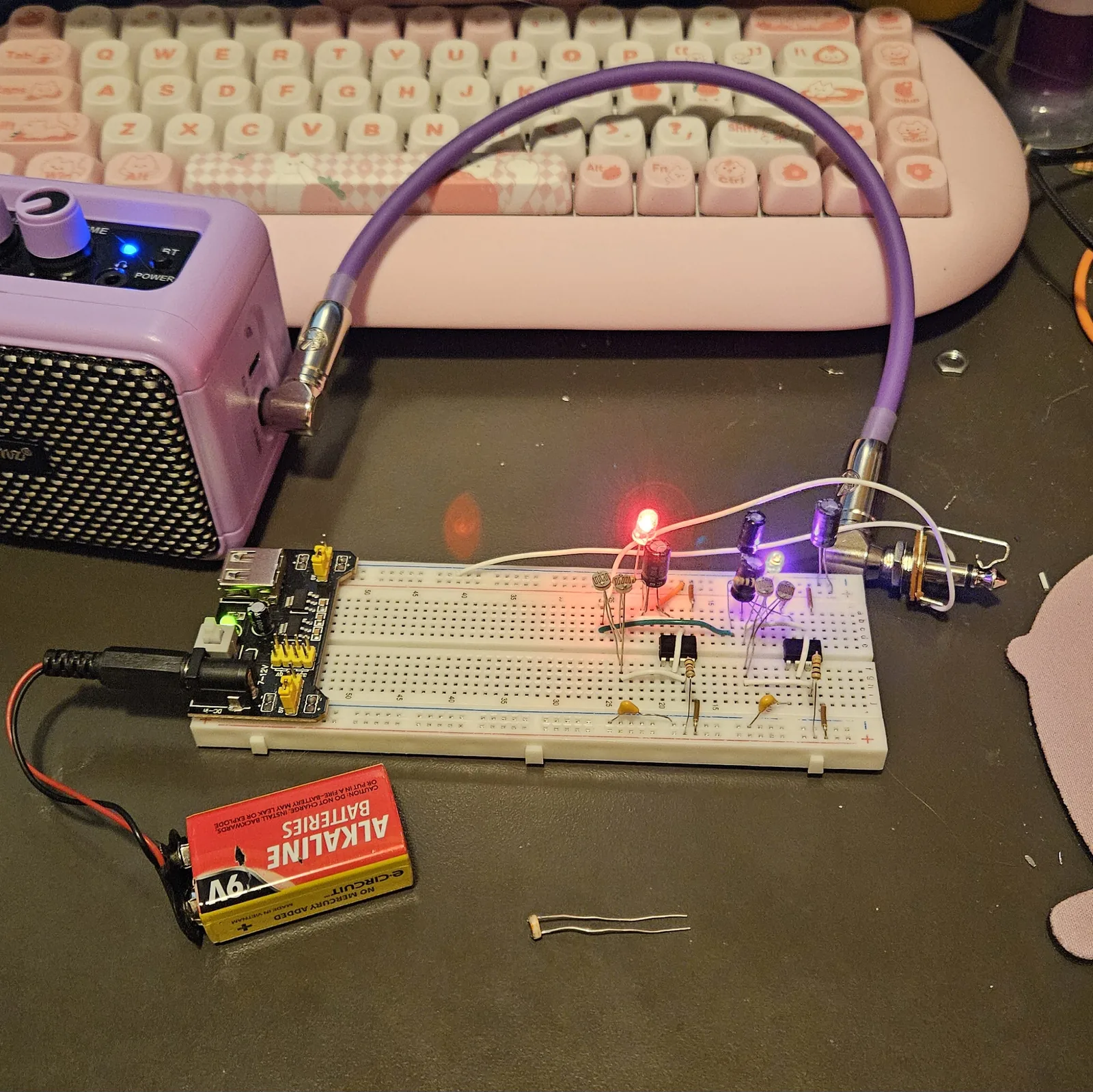
Five volts is enough. The build in the photo runs a 9V
battery into a breadboard power module, so the rails sit at 5V rather than 9V,
and with the second LED in it plays in ordinary room light. A 555 keeps oscillating down to
4.5V, so the chips are not what runs out first.
Why one LED does all that is not settled. A bright LED beside the cells is itself a light
source, and an LED across that node also clamps it the way the vactrol's does. Both are
plausible, neither has been measured, and the
stripboard version carries the same LED
in the same place as standard.
| Step | Do |
|---|---|
| 33 | 9V in: + to the + rail, − to the − rail. You should get a pulse - a repeating chirp or swoop, one per flash of the vactrol. A hand over the tempo eye changes the rate; a hand over the pitch eye bends the note |
If it does not work
| Symptom | Check |
|---|---|
| Nothing at all, dead silent | Split rails - jumper both halves. Then check every chip has pin 1 to −, pin 8 to +, pin 4 to +. Then check the notches both point left. Then look under both chips for a folded leg. |
| A steady tone, no pulsing | The tempo half is not running. C1's stripe should be on the − rail, not in B12. Check the tempo eye's leads really are in D12 and G12 - one leg on each island, not both on the same one. |
| Pulses, but the pitch never moves | The vactrol. Either the LED is in backwards (anode in C10) or the wrap is leaking light. Cover the whole lump with your hand in a dark room - if the sound changes, it is leaking. |
| Ticking or clicking instead of a note | The audio 555 has fallen below hearing. Your pitch cell's dark resistance is too high. Swap it for a faster cell, or drop C4 from 100nF to 10nF to lift the whole range. |
| A note, but it will not get low | The opposite problem - the cell never gets resistive enough. Put a 100k trimmer in series with it, or go up to 1µF for C4. |
| Very quiet | Check the second LED is in A22 first - without it this build is much quieter. After that: R2 and R4 throw most of it away by design. Feed an amp instead of a speaker, or drop them to 47R - do not go below that or the two halves start modulating each other through the mixer. |
| Hum under everything | Check C7 is actually across the rails and its stripe is on −. If it is a mains supply, the cells may also be reading the flicker off your room lights - try it on a battery to tell the two apart. |
| Hot chip | Power off immediately. A 555 that gets warm has pin 1 and pin 8 swapped, or an electrolytic in backwards nearby. |
How it works, in one breath
Two 555s, both wired as astables. IC1 is the slow one - its timing resistor is a light-dependent cell you point at the room, so covering it slows the pulse and brightening it speeds up. Its output drives an LED, and that LED is sealed face to face with a second cell in a light-tight tube. That second cell is the timing resistor for IC2, the audio oscillator. So every pulse from the slow half bends the pitch of the fast half.
A third cell - the pitch eye - sits across the same node with its face out of the box, so your hand plays it too. Two cells in parallel means whichever is letting more light through wins. Both 555 outputs are mixed through 100R resistors into one speaker, so you hear the ticking and the tone together. The mixer is lossy on purpose: it keeps the two chips from fighting each other, and a 555 into a small speaker is loud enough without help.
Things to try
The first five are fitted and working on my own board. The rest are suggestions I have not all tried. Either way the optical arrangement underneath is untouched - the vactrol, the two exposed cells and the two LEDs still do exactly what the build says.
- A switch across the tempo eye (on my board). A jumper and a toggle in parallel with it - any free hole in column 12 on each island, which is the same node the eye sits on. Closed, it shorts the eye out and the tempo half runs so fast that the pulsing stops being a pulse and turns into a steady tone. Open, the ticking comes back. Two fairly different instruments on one toggle. I put a second cell in parallel there first and then took it out again; the switch is the better version of the same idea.
- A 1k pot in the supply, after the power switch (on my board). A crude power starve. Wind it up and the whole rail sags: the pitch drops, the LEDs dim, and past a point they stop lighting while the box is still making noise. That is the same order of failure the stripboard build showed on a dying battery, so if you fit this, expect the LEDs to be the first thing to go.
- An amplifier board (on my board). A little LM386 module instead of running the mixer node straight at a speaker. It is louder and it stops the two 555s being asked to drive a load on their own.
- A mini mixer with a line in (on my board). So something else can play through the same speaker alongside it.
- A touch bend on a flying lead (on my board). This one hangs off the mixer above rather than off the Opto Duet itself. The mixer's third channel was going spare, so I soldered a bare wire onto the end of its mixing resistor and brought it out through the lid. Hold the probe and the bare metal of the tin at the same time and it squeals – your own skin is part of the path, so it is never quite the same twice. Touch the probe against one of the toggle switches instead and it growls. I found this one by fiddling with it, not by planning it.
- Swap C4. 10nF for a thin whistle, 100nF as drawn, 1µF for a growl. This is the single biggest change you can make and it is one component.
- Swap C1. Take the tempo capacitor down to 1µF and the tempo half climbs into audio range - the two 555s start beating against each other and it goes ring-mod.
- Put a pot in series with R1. A 100k linear gives you a manual tempo control on top of the light.
- Trimmer in series with each cell. The proper fix for a cell whose range is in the wrong place. 100k trimmer, set it once, forget it.
- Long leads on the pitch eye. Get it out on 300 mm of wire and you can play it away from the box.
- Second LED on the mixer node. Straight off A26 through a 1k to − and you get a flicker that follows the sound.
- Run it into a filter. An envelope filter after this thing is worth the trouble. It stops sounding like a circuit and starts sounding like it is talking back.
When it does what you want, the stripboard layout carries this exact circuit, so you can copy your component choices straight over.
Where mine ended up
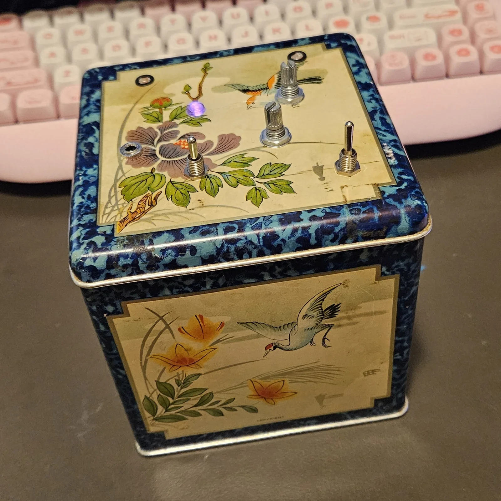
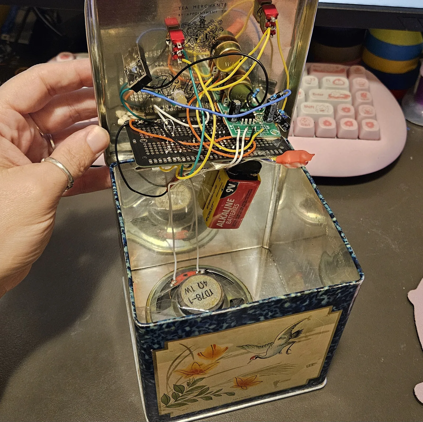
The breadboard was the workshop, not the destination. Once the mods above were settled I moved the whole thing onto a solderable breadboard - the same layout, the same holes, soldered instead of pushed in - and wired that into a tea tin. That is a reasonable way to work: prove it on the solderless board where a mistake costs seconds, then commit it once you know what you actually want.
The tin is a good enclosure for this in a way a pedal box is not. It has no panel to speak of, the lid is soft enough to drill by hand, and there is room underneath for the board, the amplifier, the mixer, a speaker and the battery all at once.
Circuit and build sheet by Onion Madder. Two 555 astables chained by a home-made vactrol.