Bazz Fuss
A single-transistor fuzz, on a breadboard · By Onion Madder · Mess O' Pedals
Christian Holmberg's fuzz, and about the smallest real one there is: one transistor, one diode, one resistor, two capacitors. Rude, gated, and synthy on the note decay - notes don't fade so much as collapse, and that collapse is the sound people build this circuit for. Build time is about ten minutes, and this one you plug a guitar into.
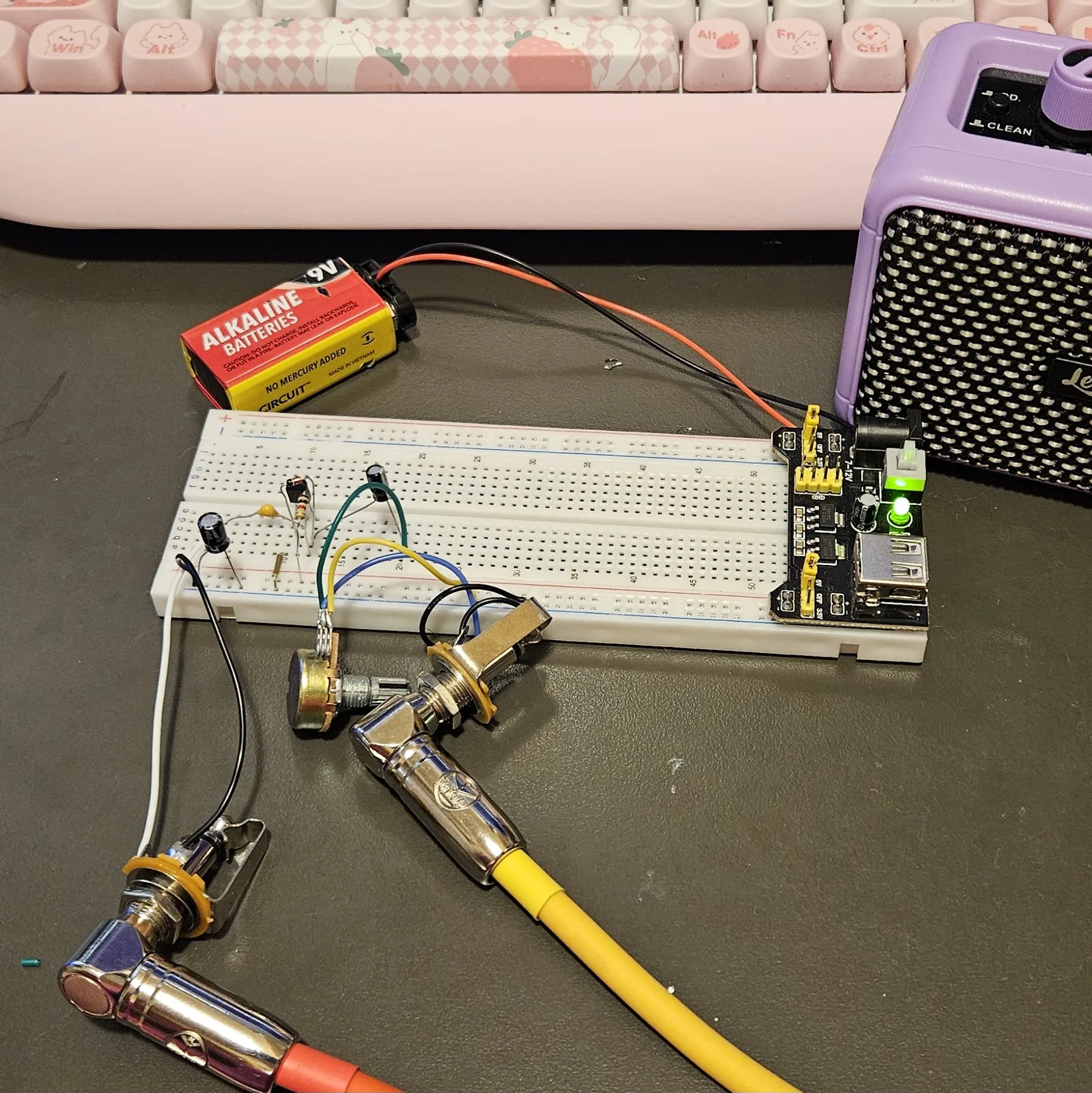
This is the third build in the breadboard series, after the Atari Punk Console and the Optical Theremin - and the first that's a proper pedal circuit, with an input jack and an output jack. Power is 9V DC - a 9V battery, or vape cells in series.
⚠ Before you start tap to expand / collapse
Two parts care which way around they go: the diode (the band goes toward the base - backwards and nothing works at all) and the two electrolytics (the stripe marks the minus leg). Get those right and there's nothing here that can hurt you or the parts.
Mind your power leads - 9V positive to the + rail, negative to the − rail, and nothing in this build should ever get warm.
If you power it from a salvaged lithium pack, the usual cell cautions apply - see Do You Want to Survive the Vapocalypse?
What you'll need
tap to expand / collapse
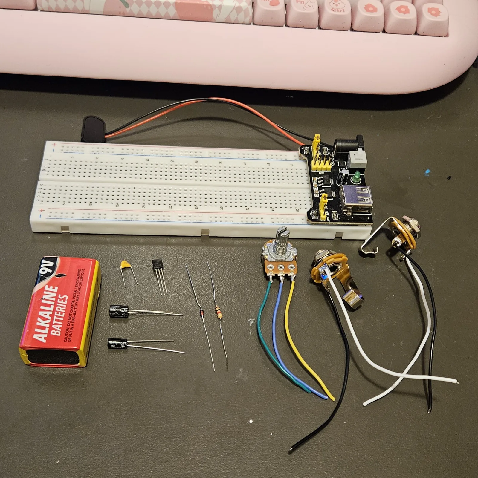
The parts list lives on the build sheet too - this version adds how to spot each part: the printed marking, the package, or the polarity clue.
- 1× 2N3904 or 2N5088 NPN transistor, TO-92 - spot it: the little half-cylinder with three legs and one flat face, part number printed on the flat
- 1× 1N914 or 1N4148 silicon diode - spot it: a tiny glass bead with a band at one end; the band marks the cathode, and where it points is the whole build
- 1× 100K resistor - spot it: bands brown-black-yellow, or meter it
- 1× 100nF film or ceramic - input cap. Spot it: printed 104. Either way around
- 1× 4.7 µF electrolytic - output cap. Spot it: a little can; the stripe marks the minus leg, longer leg is +
- 1× 100K pot - volume. Spot it: marked B100K
- 1× 100 µF electrolytic - supply smoothing. Same stripe rule
- 1× jumper wire - yes, just the one
- Breadboard, 9V supply, two jacks - input and output
- For the optional nastier version: 1× MPSA13 Darlington transistor and 1× 10K resistor (bands brown-black-orange)
Reading the breadboard
Letters run along one edge of the board and numbers along the other. A hole is a letter plus a number - E10 is row E, column 10 - and the five holes in a bank that share a number are one electrical point: A10, B10, C10, D10 and E10 are the same node with five ways in. Turn the board so the numbers climb left to right; the whole build lives in the A to E bank and the pair of rails beside it - the F to J bank stays empty.
Check your power rails aren't split at the middle of the board. If they are, jumper across the break at both ends.
Quick reference - the whole build on one card
No 14-pin chip this time - the whole thing hangs off three transistor legs. Hold it right and the holes fall into place; this is the bench card.
Emitter, base, collector - left to right, flat face toward you. Swap them and the fuzz stays silent. The diode's band goes toward the base (column 11).
The core
- Emitter (E10) → − rail via A10
- 100K: collector (B12) → + rail
- Diode: C12 → C11, band in C11
In
- 100nF: D4 → base (D11)
- Input jack tip → A4
- Input jack sleeve → − rail
Out
- 4.7µF: + leg D12 → D20
- Row 20 → volume pot → output jack tip
- Output jack sleeve → − rail
Power
- 100µF across the rails, + leg in +
- 9V: positive → + rail, negative → − rail
Steps 1–3 The semiconductors
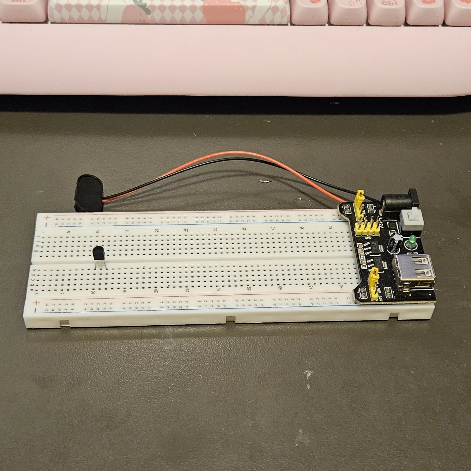
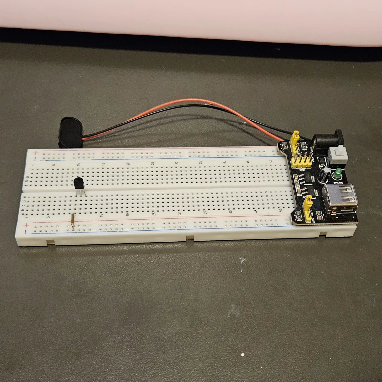
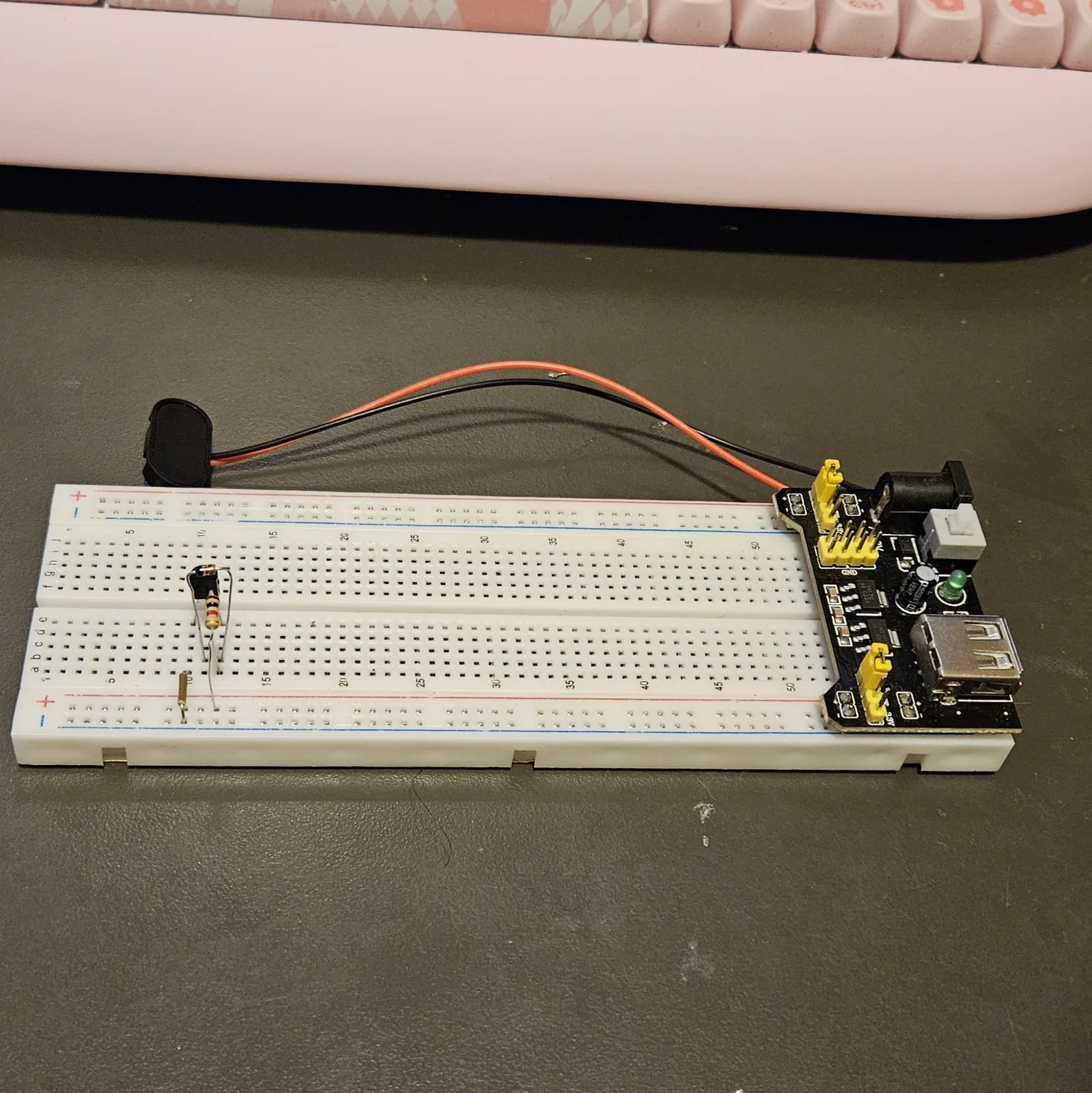
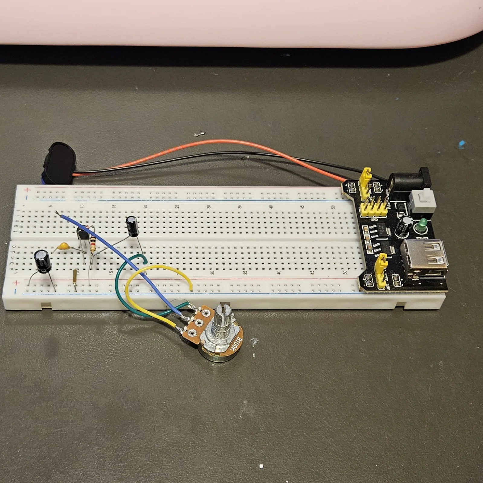
Transistor first, then the jumper that ties its emitter down, then the diode. Get the three legs the right way around and the rest of this build is pushing parts into rows.
| Step | Do |
|---|---|
| 1 | Hold the transistor with the flat face toward you and the legs pointing down. Left to right the legs are emitter, base, collector. Spread them and push them into E10, E11 and E12 in that order |
| 2 | Jumper: A10 to the − rail (emitter) |
| 3 | Diode: C12 to C11, with the banded end in C11. The band goes toward the base. Backwards and nothing works at all |
There is no bias network here, which is the whole trick. The diode in step 3 does two jobs at once: it trickles just enough current into the base to switch the transistor on, and it clips the signal at the same time. That is why the orientation matters so much and why the circuit is so short.
Steps 4–7 The passives
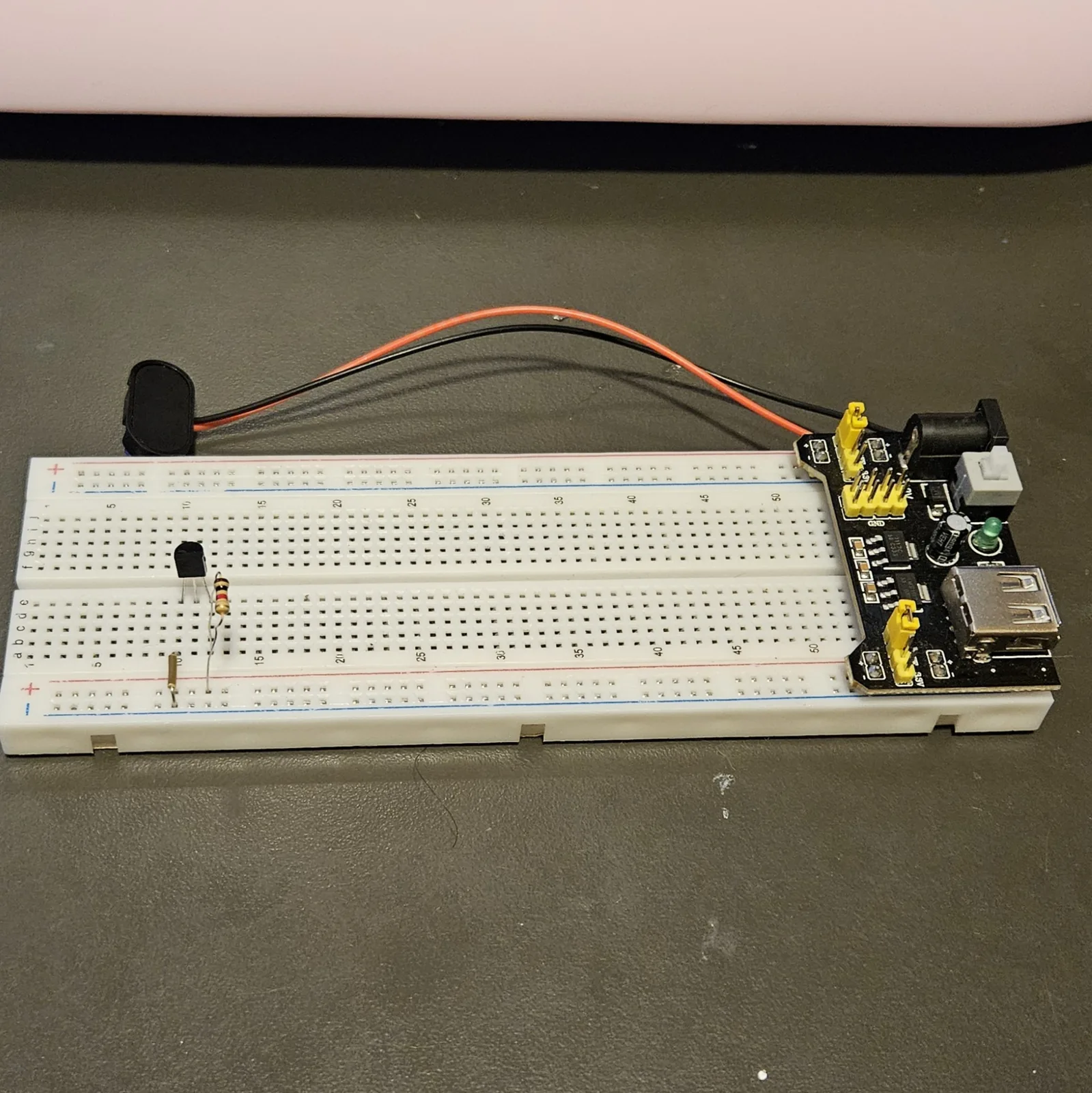
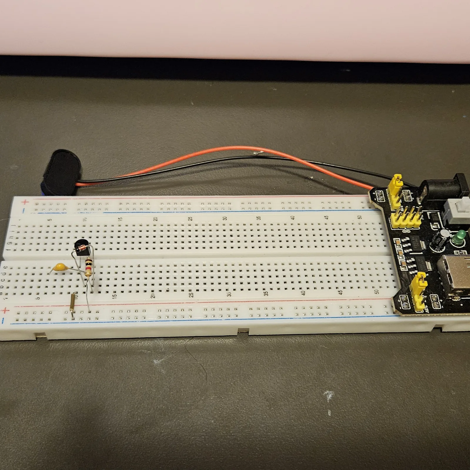
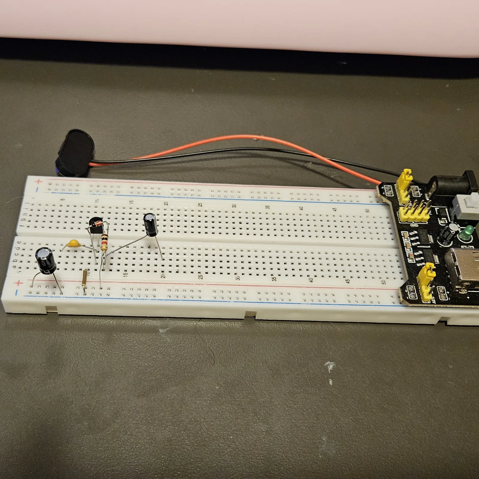
Resistor, then the film cap, then the two electrolytics. Same order every time, so you can see at a glance what is still missing from the board.
| Step | Do |
|---|---|
| 4 | Resistor 100K: B12 to the + rail |
| 5 | Cap 100nF: D4 to D11. Either way around |
| 6 | Cap 4.7 µF, + leg in D12, other leg in D20 |
| 7 | Cap 100 µF, + leg in the + rail, other leg in the − rail |
Steps 8–13 Off the board: pot and jacks
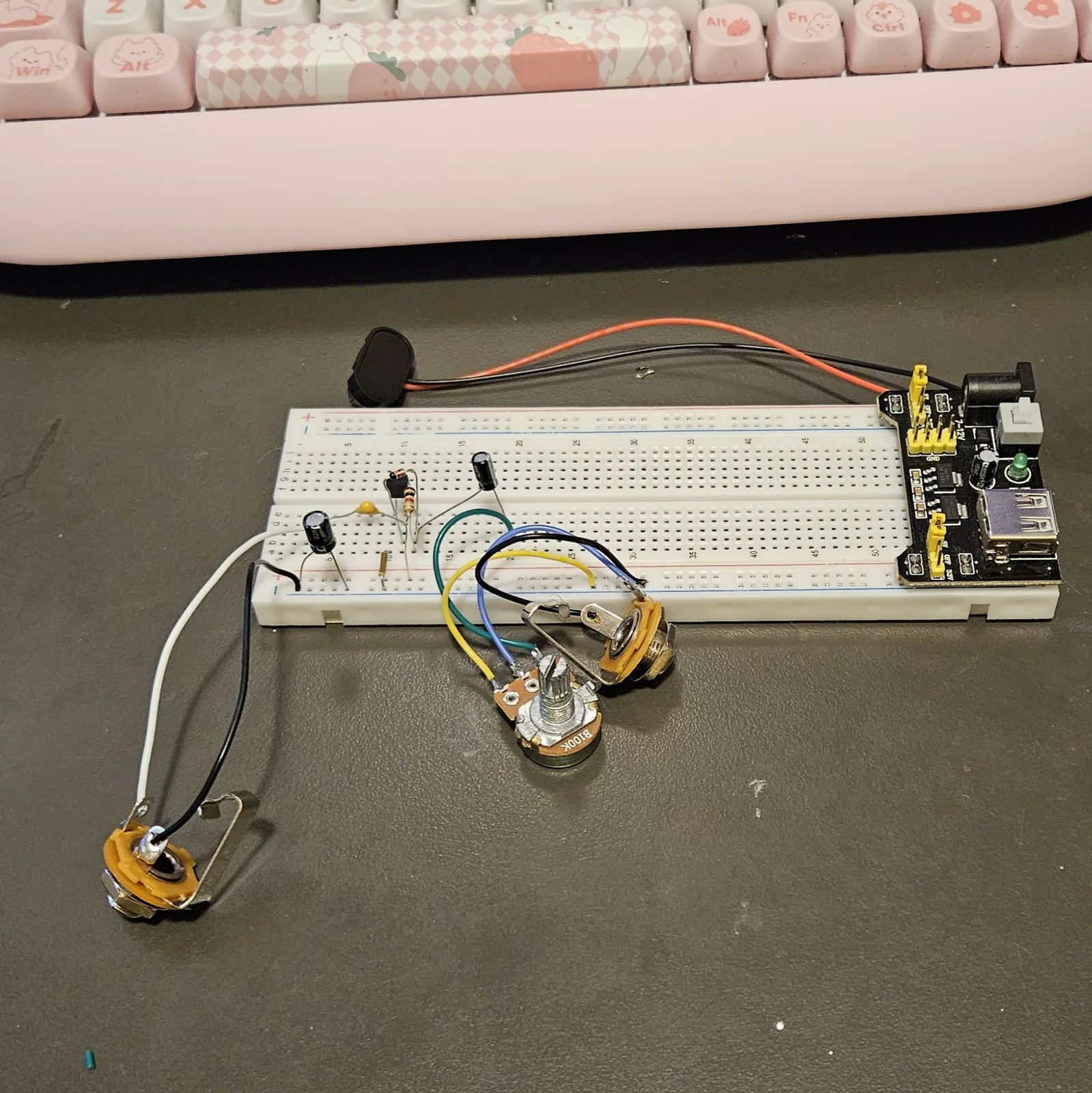
Nothing else goes into the breadboard. The volume pot and both jacks live on flying leads, so this is the part you unplug when you want the board back.
| Step | Do |
|---|---|
| 8 | Wire: A20 to either outer lug of the volume pot |
| 9 | Wire: the volume pot's other outer lug to the − rail |
| 10 | Wire: the volume pot's middle lug to the output jack tip |
| 11 | Wire: output jack sleeve to the − rail |
| 12 | Wire: input jack tip to A4 |
| 13 | Wire: input jack sleeve to the − rail |
Step 14 Power up
| Step | Do |
|---|---|
| 14 | Power: 9V positive to the + rail, negative to the − rail |
⚠ If it doesn't work
| Symptom | Check |
|---|---|
| No sound at all | Step 3, the diode is backwards. This is the fault almost every time. |
| Still no sound with the diode right | Step 1 - the transistor legs are in the wrong order. Emitter, base, collector, left to right, flat face toward you. |
| Notes choke off and die early | That's the circuit, not a fault. Roll your guitar volume back if you want less of it. |
| Very dark and woolly | Step 5. Try 10nF (printed 103) instead for a thinner, spikier sound. |
| Thin and weak | Step 5 the other way - try 1 µF. |
| Hiss and squeal with nothing plugged in | Transistor gain too high for this build. Try a 2N3904 instead of a 2N5088. |
Optional A nastier version
Swapping the transistor for a Darlington - two transistors in one package - raises the gain enormously. It needs a smaller collector resistor to stay usable.
| Step | Do |
|---|---|
| 15 | Replace the transistor in step 1 with an MPSA13, same leg order, same three rows |
| 16 | Replace the 100K in step 4 with a 10K resistor, same two points |
The 100K belongs to the plain transistor version and the 10K to the Darlington. Using the wrong one is why most Bazz Fuss builds on the internet are reported as too quiet or too wild.
How it works, in one breath
A transistor needs a trickle of current into its base before it does anything, and normally that takes a pair of biasing resistors. Here the diode does it - current dribbles from the collector through the diode into the base, parking the transistor barely switched on - and it clips the signal at the same time, two jobs with one part. Because the transistor is barely on, even a small guitar signal slams it into its limits both ways; and as a note decays the bias slides back toward off, so the sound gates out. That's the whole circuit, and why it's so short.
Things to try
- Swap the diode. A germanium 1N34A is softer and quieter, an LED clips higher and louder and cleans up more, two silicon diodes in series gets closer to a proper fuzz.
- Tame the gate. Add a resistor from A10 to the − rail instead of the jumper in step 2. Anything from 100 Ω to a few K drags it from fuzz back toward overdrive.
- Starve it. Run it on less than 9V. Four or five volts is where it gets properly sick.
- Turn it up. Put it in front of the mini amp and turn both up.
The Bazz Fuss is Christian Holmberg's circuit - shared free on his home-wrecker.com site and built by thousands since as a first pedal. This breadboard recipe, wiring, and words are my own. Build it, bend it, make it yours.