Master Divider on a Breadboard
A CD4060 that clocks itself, seven octaves on seven switches · By Onion Madder · Mess O' Pedals
The Grub Divider needs something plugged into it. This one does not. A CD4060 is a chain of fourteen flip-flops with an oscillator built into the same chip, so it can be its own clock: three parts on three pins and it runs, a pitch knob sets how fast, and seven octaves below it come out on seven switches through the Grub's weighted resistors onto one bus. An LED blinks two octaves below the lowest switch, so you can see it counting. A three-way mode switch lets an outside signal replace the clock, or just tug at it.
Why it clocks itself: the 4060 hides its first three octaves. The chip has no pins for the first three stages, or for the eleventh, so its first output is the clock divided by 16. Feed it a guitar at 110 Hz and the top switch gives you about 7 Hz. That makes it a poor divider for outside sounds and a very good one for its own oscillator, which you just tune sixteen times higher than the note you want. With the parts below the oscillator sweeps from about 450 Hz to 20 kHz, so the top switch plays from about 28 Hz to 1.3 kHz while the bottom switch ticks from under one click a second to about 20. One knob moves a chord of subharmonics and a rhythm at the same time.
⚠ Before you start tap to expand / collapse
The 2.2K is not optional. R12 sits in series with the pitch pot. The pot is wired as a variable resistor, so at one end of its travel it is zero ohms, and with nothing in the way the oscillator's timing resistor disappears. The 2.2K is this build's version of the 1K every other pitch pot on this site gets, and it is also what sets the top of the sweep at about 20 kHz.
Two pots, wired two ways. The pitch pot is a variable resistor: wiper tied to one outer lug, 2.2K in series. The volume pot is a divider: all three lugs used, signal on one outer, ground on the other, wiper out. Wire the volume pot like the pitch pot and it will not turn anything down.
Two parts care which way around they go. The 10 µF electrolytic has a stripe down one side marking the minus leg, and the LED's long leg is the plus. Everything else is a resistor or a ceramic and does not care.
The 100K on pin 12 is not optional either. Pin 12 is RESET, and on this chip RESET held high does two things: it clears the count and stops the oscillator. Left floating it picks up whatever is nearby and the whole thing stutters or goes silent. The 100K holds it low so it runs.
Meter your rails before you wire anything. This layout runs from column 13 to column 51, straight across the midpoint where plenty of full-size boards break their rails, and it uses both rail pairs. A split rail is the single most common reason a breadboard build does nothing at all.
What you'll need
tap to expand / collapse
The parts list lives on the build sheet too - this version adds how to spot each part in a drawer.
- 1× CD4060 14-stage ripple counter with oscillator, DIP-16 (IC1) - spot it: sixteen legs, 4060 in the part number, a notch at one end and a dot beside pin 1. A CD4040 or CD4020 has the same family look and no oscillator; it will not run on its own
- 1× LED (LED1), any color - spot it: the long leg is the plus. It blinks with the count
- 7× the weighted ladder, one resistor per octave and every value different: 1M (brown-black-green), 470K (yellow-violet-yellow), 220K (red-red-yellow), 100K (brown-black-yellow), 47K (yellow-violet-orange), 22K (red-red-orange), 10K (brown-black-orange) - R1 to R7. They are what make this a mixer instead of a selector, the same ladder as the Grub
- 2× 100K resistor (R8, R9) - spot it: brown-black-yellow, the same as the ladder's 100K. The RESET pull-down and the input pull-down. Three 100Ks in all; lay them out together
- 1× 220K resistor (R11) - spot it: red-red-yellow, the same as the ladder's 220K. This one is Rs, the oscillator's input resistor. Two 220Ks in all
- 1× 2.2K resistor (R12) - spot it: red-red-red. The floor under the pitch pot. See the note above
- 1× 4.7K resistor (R13) - spot it: yellow-violet-red. Keeps the LED's current down to something the chip's output can give it
- 1× 1K resistor (R10) - spot it: brown-black-red. On the output, after the cap
- 1× 100pF ceramic (C4) - spot it: a tiny disc printed 101. The SYNC cap, and the one value on this list that is a guess. See Things to try
- 1× 10nF ceramic (C3) - spot it: disc printed 103. The oscillator's timing cap. A smaller one moves everything up, a bigger one moves everything down
- 1× 100nF ceramic (C1) - spot it: disc printed 104. Supply decoupling, next to the chip
- 1× 10 µF electrolytic (C2) - spot it: a small can with a stripe down one side. Blocks the DC on the way out
- 1× 100K linear pot (B100K), the pitch knob - spot it: a B before the value means linear. Wired as a variable resistor, wiper tied to one outer lug
- 1× 100K linear pot (B100K), the volume knob - the same part, wired as a divider, all three lugs used
- 7× SPST switch - the octaves, one each. Any on-off toggle
- 1× SPDT on-off-on toggle - the mode switch. spot it: three lugs, and the lever stays put in the middle. The middle position is INT, the chip on its own clock; one side is EXT, the other is SYNC
- 1× momentary pushbutton - optional. Hold it and the chip stops; let go and the count starts again from the top
- 2× jack - one in, one out
- A full-size breadboard, 63 columns, both banks and both rail pairs - this layout runs from column 13 to column 51, so a half-size board will not fit it as drawn. Plus four jumpers
- 9V battery and a snap. A CD4060 runs anywhere from 3V to 15V; at least two vape cells in series (7.4V; three gives 11.1V) or a 9V battery
Reading the breadboard
This guide names exact holes, like E20 or J38. Letters run across the board and numbers run along it, and both are printed on the board itself, so every instruction below points at one hole you can put a finger on.
The center channel splits the letters into two banks: A to E on one side and F to J on the other, with E and F being the two rows either side of the channel. The five holes in a bank that share a number are all the same electrical point, which is why a step sometimes names a different row than you would expect - any free hole in that column and bank will do.
Turn the board so the numbers climb left to right. Then A to E is the lower bank and F to J the upper bank, the top rails are the pair above F to J and the bottom rails are the pair below A to E. This build uses both banks and both rail pairs. Before you wire anything, meter each rail end to end; if yours is split, bridge each half with a jumper first.
Several resistors here are long, and some reach over holes. The 1M runs from B26 to B34, eight columns. Bend its legs wide and let it arch; a part lying over a hole it does not use is not connected to it. The upper bank is the oscillator, the mode switch and three octaves; the lower bank is the other four octaves, the LED and the output. Column 17 has a part in both banks and they are not the same point - the channel keeps them apart.
Quick reference - the whole build on one card
The pinout with the hole every pin lands in, labeled by what each pin does in this circuit. The steps below walk through it slowly; this is the bench card.
The notch points left and pin 1 goes in E20, so pin 16 lands in F20 directly across the channel. The octave outputs are scattered around the chip in no order at all - Q4 to Q7 in the lower bank, Q8 to Q10 in the upper - which is the datasheet's doing, not this layout's. Q13 and Q14 are outputs left unconnected, which is fine; an unused output needs nothing.
Power and the LED
- Bridge + → + and − → − between the top and bottom rail pairs
- J20 → top + rail (pin 16); A27 → bottom − rail (pin 8)
- 100nF across the top rails, near column 20
- 4.7K: B20 → B13; LED long leg A13, short leg bottom −
The oscillator and reset
- 220K: G25 → G30; 10nF: H27 → H30
- 2.2K: I30 → I35; pitch pot J26 ↔ J35
- 100K: J24 → top − (reset held low)
- Momentary H24 ↔ top + (optional)
The seven octaves
- Q4 1M B26 → B34; Q5 470K D24 → D30
- Q6 220K D23 → D17; Q7 100K C25 → C32
- Q8 47K I22 → I19; Q9 22K G23 → G17; Q10 10K H21 → H15
- Switches: A34, A30, C17, A32, J19, J17, J15 → all to A40
Modes and out
- Input tip H38; 100K J38 → top −
- Mode: middle lug I38, EXT lug H25, SYNC lug J28; 100pF I25 → I28
- Volume: B40 → lug 1, bottom − → lug 3, wiper → D44
- 10µF: + C44, stripe C47; 1K B47 → B51; jack tip A51
- Every octave meets at A40 and nowhere else
Step 1 The chip
It goes in dry, before a single wire. Sixteen legs is two more chances than usual to fold one under the body, and every other part on the board is measured from this footprint.
| Step | Do |
|---|---|
| 1 | Seat the CD4060 (IC1) across the center channel, notch to the left: pin 1 in E20, pin 8 in E27, pin 9 in F27, pin 16 in F20. The lower bank then reads E20 = 1 through E27 = 8, and the upper bank reads F27 = 9 back to F20 = 16. Press it flat and check no leg folded under |
Step 2 The LED
The other semiconductor, so it goes in with the chip.
| Step | Do |
|---|---|
| 2 | LED1: long leg in A13, short leg in the bottom − rail. Its resistor arrives at step 19 |
Steps 3–6 The jumpers
Four wires, all plumbing. The chip takes its supply from the top rails and its ground from the bottom ones, so the two rail ties are not optional.
| Step | Do |
|---|---|
| 3 | J1: bottom + rail to top + rail. Ties the two positive rails together |
| 4 | J2: bottom − rail to top − rail. Ties the two negative rails together |
| 5 | J3: J20 to the top + rail. This is pin 16, the chip's supply |
| 6 | J4: A27 to the bottom − rail. This is pin 8, the chip's ground |
Steps 7–19 The resistors
Thirteen of them. The first seven are the ladder, one per octave in pitch order, and every value is different - check the bands on each one rather than trusting the one before it. The highest octave gets the biggest resistor, so it sits quietly on top of the low ones instead of burying them.
| Step | Do |
|---|---|
| 7 | R1, 1M (brown-black-green): B26 to B34. Q4, the clock divided by 16 - the highest octave and the quietest |
| 8 | R2, 470K (yellow-violet-yellow): D24 to D30. Q5, divided by 32 |
| 9 | R3, 220K (red-red-yellow): D23 to D17. Q6, divided by 64. This one runs left, the others in the lower bank run right |
| 10 | R4, 100K (brown-black-yellow): C25 to C32. Q7, divided by 128 |
| 11 | R5, 47K (yellow-violet-orange): I22 to I19. Q8, divided by 256. Upper bank now |
| 12 | R6, 22K (red-red-orange): G23 to G17. Q9, divided by 512 |
| 13 | R7, 10K (brown-black-orange): H21 to H15. Q10, divided by 1024 - the lowest octave and the loudest. At most settings of the pitch knob this one is a tick, not a note |
| 14 | R8, 100K (brown-black-yellow): J24 to the top − rail. Holds RESET low so the chip runs |
| 15 | R9, 100K: J38 to the top − rail. The input pull-down, so an empty input jack is quiet rather than random |
| 16 | R10, 1K (brown-black-red): B47 to B51. On the output, after the cap |
| 17 | R11, 220K (red-red-yellow): G25 to G30. Rs, from the oscillator's input pin to the timing node at column 30 |
| 18 | R12, 2.2K (red-red-red): I30 to I35. The floor under the pitch pot. Not optional |
| 19 | R13, 4.7K (yellow-violet-red): B20 to B13. From Q12 to the LED's long leg |
Steps 20–22 The ceramic caps
None of these care which way around they go.
| Step | Do |
|---|---|
| 20 | C1, 100nF (printed 104): top + rail to top − rail, as close to column 20 as you can get it. Supply decoupling. It does nothing useful far away from the chip |
| 21 | C3, 10nF (printed 103): H27 to H30. The timing cap, from pin 9 to the timing node. This and the pitch knob set the speed of everything |
| 22 | C4, 100pF (printed 101): I25 to I28. The SYNC cap, from pin 11 to the SYNC lug's column. It does nothing until the mode switch selects it |
Step 23 The electrolytic
One part, and the only cap on the board with a direction.
| Step | Do |
|---|---|
| 23 | C2, 10 µF electrolytic: plus leg in C44, the volume wiper's column, stripe leg in C47. The stripe points away from the chip, toward the jack |
Steps 24–38 Off the board: the knobs, the switches and the jacks
Everything with a wire on it. The octave switches are one step each, in pitch order, so you can tick them off as you go.
The PITCH pot is a variable resistor. Tie the wiper to one outer lug and run that pair to J26; the other outer lug goes to J35. The 2.2K you fitted at step 18 is what protects the fast end.
The VOLUME pot is a divider. All three lugs do a job: signal in on one outer, ground on the other, wiper out. Nothing is tied together and there is no resistor in front of it, because a divider at zero should be silent.
The mode switch is an on-off-on, and its middle lug is the common. Middle position, nothing connected: the chip runs on its own oscillator. Flip it one way and the input jack goes straight to pin 11; flip it the other and it goes through the 100pF. Which side is EXT depends on how you mount it, so label it once you have heard it.
| Step | Do |
|---|---|
| 24 | Power in: 9V snap red to the bottom + rail, black to the bottom − rail. Leave it unplugged until step 40 |
| 25 | The pitch pot, wired as a variable resistor: wiper and one outer lug together to J26, the other outer lug to J35. If the knob turns the wrong way for you, swap which outer lug is tied to the wiper |
| 26 | Octave switch 1 (Q4, ÷16): one side to A34 |
| 27 | Octave switch 2 (Q5, ÷32): one side to A30 |
| 28 | Octave switch 3 (Q6, ÷64): one side to C17, lower bank |
| 29 | Octave switch 4 (Q7, ÷128): one side to A32 |
| 30 | Octave switch 5 (Q8, ÷256): one side to J19 |
| 31 | Octave switch 6 (Q9, ÷512): one side to J17, upper bank. Not the same point as C17 |
| 32 | Octave switch 7 (Q10, ÷1024): one side to J15 |
| 33 | The bus: wire the other side of all seven switches together, off the board, and run one lead from that chain to A40. This is the mixer - seven octaves arriving through seven resistors onto one point |
| 34 | The volume pot, wired as a divider - all three lugs used. One outer lug to B40, the bus; the other outer lug to the bottom − rail; wiper to D44, the plus side of the 10 µF. If it runs backwards, swap the two outer leads |
| 35 | Output jack: tip to A51, sleeve to the bottom − rail |
| 36 | Input jack: tip to H38, sleeve to the top − rail |
| 37 | The mode switch, on-off-on: middle lug to I38; one outer lug to H25, which is EXT, straight to pin 11; the other outer lug to J28, which is SYNC, through the 100pF |
| 38 | The retrigger, optional: a momentary between H24 and the top + rail. Hold it and pin 12 goes high, which clears the count and stops the oscillator; let go and it starts again from the top. Leave it out and nothing changes |
Steps 39–41 Check, then power up
Now, and not before. Everything above goes in with the supply disconnected.
Start with the volume knob down. Seven CMOS outputs summed onto one bus is a hot square wave by the standards of anything expecting a guitar. Turn it up into the amp rather than the other way around.
| Step | Do |
|---|---|
| 39 | Supply off. Check the chip's notch points left, the 10 µF's stripe is in C47, the LED's long leg is in A13, and the 2.2K really is red-red-red. Check the ladder against step 7 to step 13 one band at a time. Then meter the bottom + rail to the bottom − rail: it should read high, not near zero |
| 40 | 9V in, with the mode switch in the middle, all seven octave switches off, the pitch pot at mid travel and the volume down. The LED should start blinking - that is the chip counting, before you have heard anything. Turn the pitch knob and the blink speeds up and slows down |
| 41 | Play it. Switch on octave 1 and bring the volume up: a square wave that follows the pitch knob. Add octaves one at a time and each one lands an octave under the last, quieter ones on top, louder ones underneath. With the knob low, the bottom switches stop being notes and start being a pulse. Then try the mode switch with something plugged into the input - the Atari Punk Console is the obvious thing to feed it |
⚠ If it doesn't work
| Symptom | Check |
|---|---|
| Nothing at all, and the LED is dark. | Split rails - jumper both halves of each, then check J1 and J2 really tie the two pairs together. Then the chip: pin 16 to + at J20, pin 8 to − at A27, notch pointing left. Then look under the chip for a folded leg. Then the LED itself: long leg in A13, short leg in the − rail. |
| The LED is dark but the switches make sound. | The LED is in backwards, or the 4.7K is not reaching B20. The chip is fine; this is cosmetic. |
| The LED is lit solid, or dark, and nothing changes with the pitch knob. | The oscillator is not running. Check the mode switch is in the middle. Then the three oscillator parts: the 220K from G25 to G30, the 10nF from H27 to H30, the 2.2K from I30 to I35, and the pitch pot from J26 to J35. All three meet at column 30 and nowhere else. Then RESET: the 100K from J24 must reach the − rail, because a high pin 12 stops the oscillator dead. |
| It stutters, or stops when you touch the board. | RESET is floating - the 100K at J24 is missing or on the wrong rail. Or the retrigger button is wired to − on one side and + on the other. |
| One octave is silent. | That octave only: its ladder resistor and its switch. Check the switch hole is in the same column and bank as the resistor's far leg, and that the switch's other side made it onto the bus chain. |
| The bottom octaves sound broken - clicks, not notes. | Working as intended. Q10 is the clock divided by 1024; at most knob settings it is below the bottom of hearing and you hear the individual edges. Turn the pitch up and they become notes. |
| The pitch knob does almost nothing, or only works at one end. | It is a linear pot driving a frequency, so most of the speed change is crowded into the fast end - that much is normal. If it does nothing at all, it is wired as a divider: the wiper must be tied to one outer lug, and that pair goes to J26. |
| The pitch jumps or the top of the sweep sounds rough. | Not yet known whether this happens. The 220K is only two to ten times the timing resistor at the slow end of the knob, which is what TI asks for; at the fast end it is a hundred times. If the top of the sweep misbehaves, try a 47K or 100K there and say so. |
| EXT is silent with something plugged in. | The 4060 needs its input to swing most of the way from ground to the supply. A small or AC-coupled signal may not get there - this is the same complaint the Grub has, and a gain stage in front is the same answer. Watch the LED: if it blinks in EXT, the chip is counting and the problem is downstream. |
| EXT works but everything is very low. | Correct. The first switch is the input divided by 16, so a 1 kHz tone comes out at about 62 Hz. Feed it something high. |
| Volume works backwards. | The two outer lugs are swapped. Harmless. |
| It is horrible. | Good. |
Built, and heard
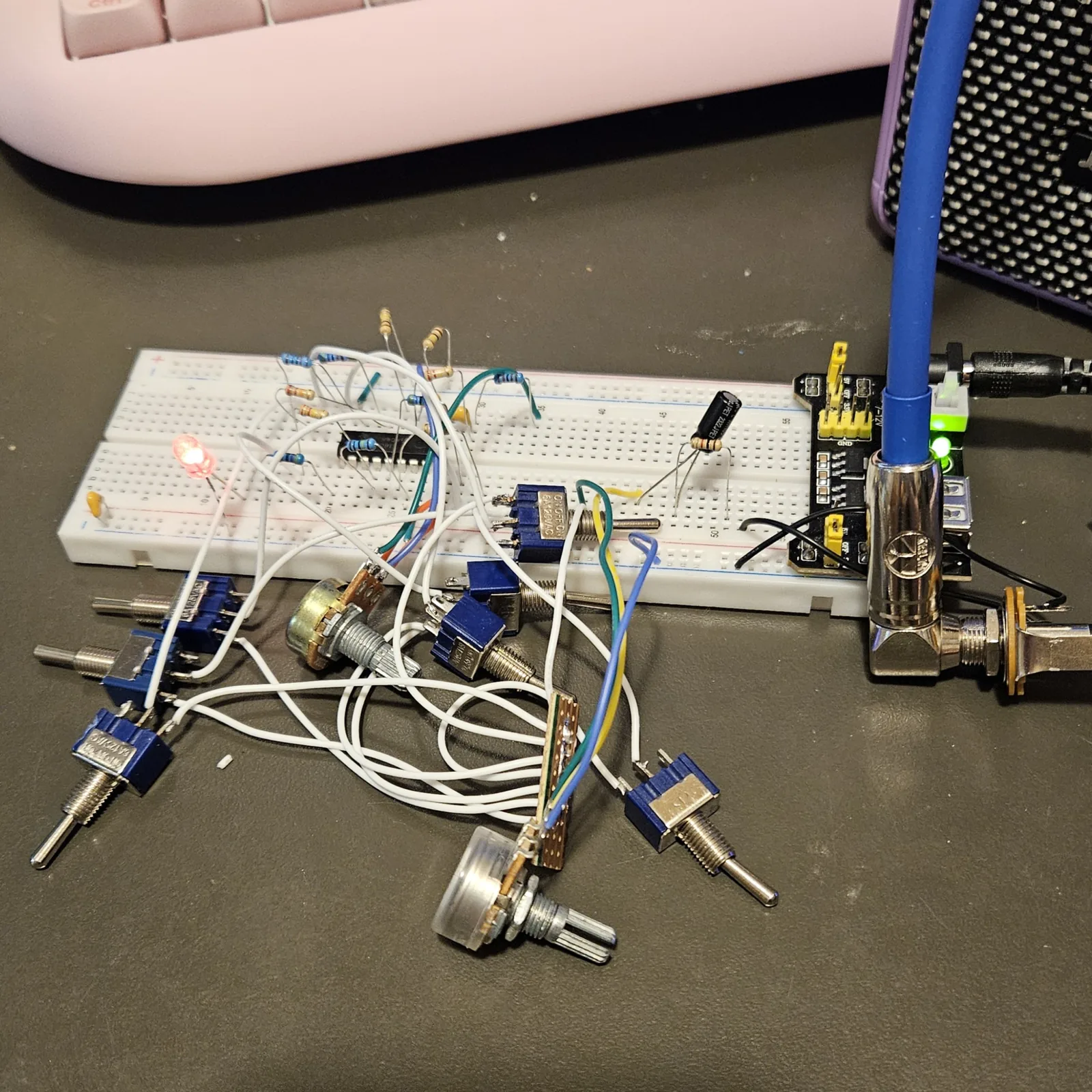
I built it on the breadboard as this page has it, except the mode switch, which I left off for testing. So INT is the mode that has been heard, and EXT and SYNC have not. It clicks rhythmically, exactly like the original divider, but with the oscillator underneath.
How it works, in one breath
Inside a CD4060 is a pair of inverters waiting to be an oscillator and a chain of fourteen flip-flops waiting to be clocked. Pin 10 drives the pitch pot and its 2.2K into a node at column 30, pin 9 drives the 10nF into the same node from the other side, and the 220K feeds that node back into pin 11: the cap charges through the pot until pin 11 crosses its threshold, both inverters flip, and the cap starts charging the other way. The speed is about 1 over 2.2 times the resistance times the capacitance, which is where the 450 Hz to 20 kHz comes from. Every flip-flop down the chain halves what it is given, so each output is an exact octave below the one before, and the chip brings out Q4 to Q10, seven in a row. Each one goes through its own resistor to its own switch and onto one bus, and the resistors run 1M down to 10K so the high octaves sit on top of the low ones instead of burying them - the Grub's trick, unchanged. Q12 is two octaves below the bottom switch, which is slow enough to see, so it drives the LED. The mode switch is the whole of the outside world: in EXT it drives pin 11 harder than the 220K can, so the outside signal becomes the clock; in SYNC it only reaches pin 11 through 100pF, so each edge of the outside signal is a short kick to the oscillator rather than a replacement for it.
Things to try
None of these have been tried yet, and neither has the mode switch.
- Change the SYNC cap. 100pF is a starting guess. Bigger kicks harder, up to the point where SYNC is just EXT; smaller lets the oscillator ignore the input. Try 47pF and 1nF and see which end is more interesting.
- Swap the timing cap. 1nF moves everything up ten times, so the bottom switch becomes a note and the top one becomes a whistle. 100nF moves everything down ten times and the whole board becomes a rhythm.
- Move the LED. Pin 2 (Q13) blinks half as fast as pin 1 and pin 3 (Q14) a quarter as fast. Move the 4.7K's leg from B20 to B21 or B22.
- Gate it from outside. RESET held high stops the oscillator, so a slow square wave from another build, wired into H24 in place of the button, chops the whole thing into bursts. Share the grounds.
- Feed it the Atari Punk Console. It is the source that made the Grub sound best, and it is high enough that dividing by 16 still leaves a note.
- Solder it down. The stripboard Master Divider is this circuit drawn in Copper Bottom, part for part.
This one is mine: the Grub's weighted switch-and-bus mix on a CD4060, with the oscillator hookup from TI's datasheet. I have built it on a breadboard, without the mode switch. Build it, bend it, make it yours.