Breadboard Hive
A six-oscillator CD40106 drone box, on a breadboard · By Onion Madder · Mess O' Pedals
The Dead-Bug Hive without the dead bug. Same six-voice CD40106 drone box, but nothing gets soldered except the pots, and a range cap swap takes two seconds instead of two minutes. If you want to know what a 1nF voice actually sounds like next to a 10 µF one, build it here first and commit later. Build time about forty minutes.
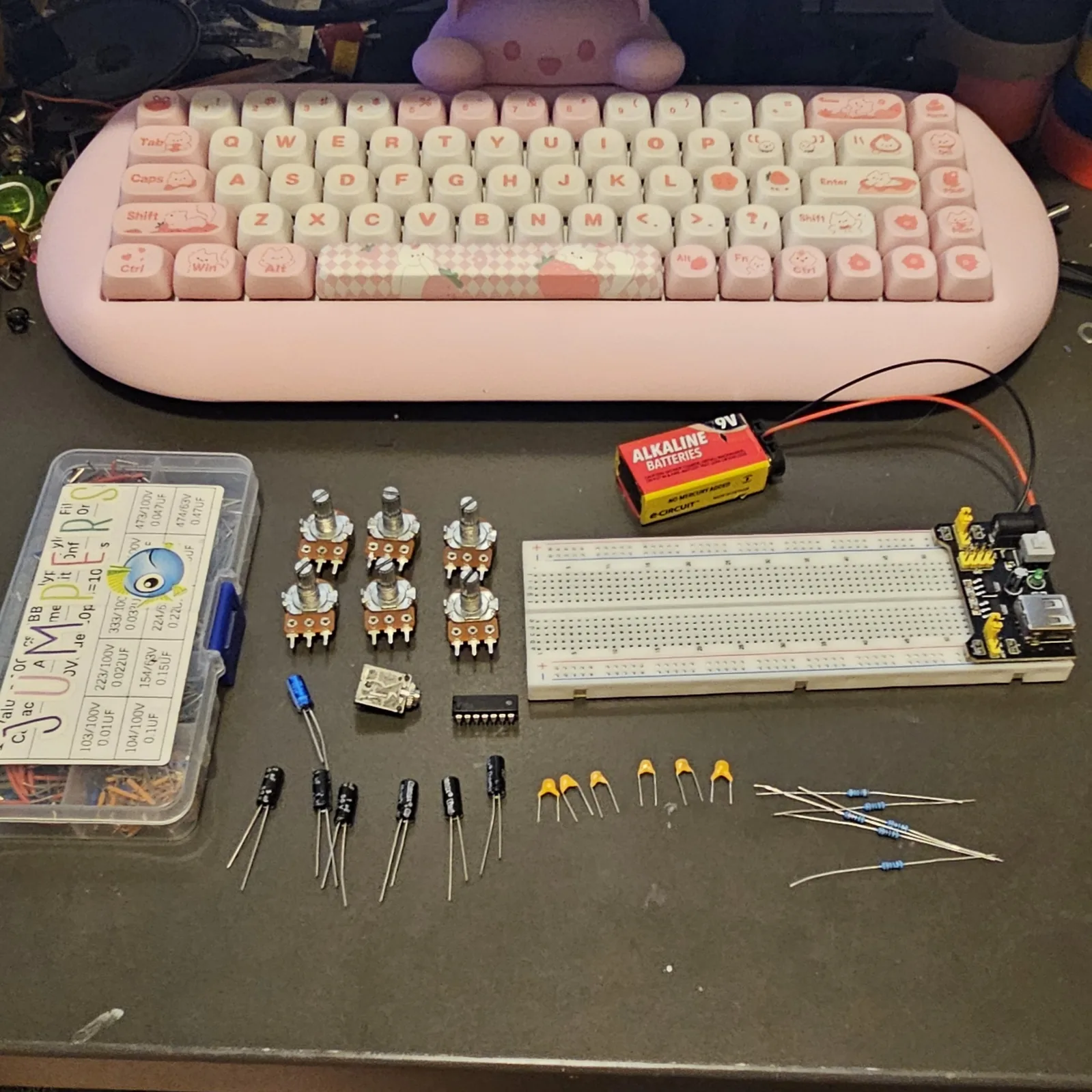
Before you start tap to expand / collapse
The CMOS rule: never leave an input floating. An unused 40106 input will pick up whatever is in the air, switch at random, and heat the chip up. Every input either has a voice hung on it or a jumper to the − rail. There is no third option, and this is the single most common way to kill one of these. Built in order, every input has its voice before power arrives at step 45 - but if you power up part-way through to test, every input that doesn't have its voice yet needs a jumper to the − rail first.
Check your power rails aren't split at the middle of the board, and check that both the top and bottom pairs are live - this build uses both. Jumper across any break, and jumper top to bottom if only one pair is fed.
The only soldering here is the six pot leads. Everything else pushes into the board.
What you'll need
tap to expand / collapse
New to the parts? Each line notes how to spot it - the printed marking, the package, or the polarity clue.
- 1× CD40106 hex Schmitt-trigger inverter, 14-pin DIP. Also sold as CD40106B or MC14106. Spot it: the part number is printed on top and a notch marks pin 1
- 6× 1M pots, linear - pitch, one per voice. Spot it: marked B for linear taper, with the value after, so B1M
- 6× 1K resistors - one per pot, soldered to the wiper. Anything 1K to 10K works; see the note under the build. Spot it: bands read brown–black–red–gold = 1, 0, ×100, so 1000 Ω
- 6× 10K resistors - mixer, one per voice. Spot it: bands read brown–black–orange
- 6× 1 µF non-polar - mixer, one per voice. Reach for film here: radial film sits on 0.2″ pitch, which is exactly two breadboard rows. Spot it: marked NP or BP if electrolytic
- 1× 0.1 µF ceramic - supply decoupling. Spot it: printed 104
- Range caps, one per voice, a decade apart, and the whole point of building it here: 1× 100pF (printed 101, the highest whistle, voice 1), 1× 1nF (printed 102, high, voice 2), 1× 10nF (printed 103, mid, voice 3), 1× 0.1 µF (printed 104, low growl, voice 4), 1× 1 µF (printed 105, sub-bass throb, voice 5), 1× 10 µF (printed 106, slow LFO clicks, voice 6 - the ceramic, not the polarised electrolytic)
- 1× 10 µF electrolytic - output DC blocker. Spot it: the stripe marks the minus leg; the longer leg is +
- 1× 100 µF electrolytic - supply smoothing
- Breadboard, 5–9V supply, output jack, jumper wire. The chip is happy anywhere from 3V to 18V, so a 5V breadboard module is fine. 9V is livelier
Reading the breadboard
Letters run along one edge of the board and numbers along the other. A hole is a letter plus a number - E10 is row E, column 10 - and the five holes in a bank that share a number are one electrical point: A10, B10, C10, D10 and E10 are the same node with five ways in. Turn the board so the numbers climb left to right, exactly as it sits in the photos.
The Hive uses both banks: the chip straddles the center channel, voices 1 to 3 build downward from row E and voices 4 to 6 upward from row F. So both rail pairs must be powered - if your supply feeds only one pair, bridge + to + and − to − at the free end of the board.
Quick reference - the whole build on one card
The pinout with its breadboard rows, plus every connection at a glance. The steps below walk through it slowly; this is the bench card.
“A” = input, “Y” = output. Keep the chip label-up with the notch to the left, put pin 1 in E10, and every pin lands on the hole shown. Voices 1 to 3 live entirely in the bottom bank, voices 4 to 6 up top.
Power (first)
- J10 → top + rail (pin 14)
- A16 → − rail (pin 7)
- 0.1 µF: G10 → top − rail
- All six inputs get a voice - none are left floating
What every voice needs
- Range cap: input column → − rail
- Pot's 1K free end → output column
- Pot outer lug → input column
- 10K: output column → mixer column
- 1 µF NP: mixer column → bus column
The six voices - in / out
- V1 → in E10 / out E11, 100pF
- V2 → in E12 / out E13, 1nF
- V3 → in E14 / out E15, 10nF
- V4 → in F15 / out F16, 0.1µF (the top bank flips!)
- V5 → in F13 / out F14, 1µF
- V6 → in F11 / out F12, 10µF
Mix → out
- Bus columns: 22, 26, 30 - both banks
- Five jumpers make them one node
- 10 µF (+ at E30) → B32
- A32 → jack tip; − rail → sleeve
Steps 1–4 Prep the pots, seat the chip
All six pots get the same treatment before anything goes near the board, then the chip and its two power jumpers. Pin 1 in E10 - put it anywhere else and every hole below shifts with it.
| Step | Do | Notes |
|---|---|---|
| 1 | Solder a 1K resistor to the wiper of all six pots, and a wire to each end of the pair | The three joints below, six times |
| 2 | CD40106 across the center channel | Notch to the left: pin 1 in E10, pin 7 in E16, pin 8 in F16, pin 14 in F10 |
| 3 | Jumper: J10 → top + rail | pin 14 |
| 4 | Jumper: A16 → − rail | pin 7 |
Steps 5–9 The bus jumpers
Five jumpers turn rows 22, 26 and 30 on both sides into one node. Do them now, while the board is still empty enough to see what you are doing.
| Step | Do | Notes |
|---|---|---|
| 5 | B22 → B26 | - |
| 6 | C26 → C30 | - |
| 7 | I22 → I26 | - |
| 8 | H26 → H30 | - |
| 9 | D30 → G30 | The one that links the two halves |
Steps 10–15 The six mixer resistors
Six identical 10K resistors, one per voice, each from that voice's output row to its mixer row. Same part six times, so this goes quickly.
| Step | Do | Notes |
|---|---|---|
| 10 | 10K: B11 → B20 | Mixer resistor |
| 11 | 10K: B13 → B24 | Mixer |
| 12 | 10K: B15 → B28 | Mixer |
| 13 | 10K: I16 → I28 | Mixer |
| 14 | 10K: I14 → I24 | Mixer |
| 15 | 10K: I12 → I20 | Mixer |
Steps 16–22 The ceramics
The six range caps are the only parts on this board that differ from each other, and they are what makes six voices instead of six copies of one. Check each value against the card above as you go. The decoupling cap goes in with them.
| Step | Do | Notes |
|---|---|---|
| 16 | 100pF (101): B10 → − rail | Voice 1 range cap |
| 17 | 1nF (102): B12 → − rail | Voice 2 range cap |
| 18 | 10nF (103): B14 → − rail | Voice 3 range cap |
| 19 | 0.1 µF (104): I15 → top − rail | Voice 4 range cap |
| 20 | 1 µF (105): I13 → top − rail | Voice 5 range cap |
| 21 | 10 µF (106): I11 → top − rail | Voice 6 range cap |
| 22 | 0.1 µF: G10 → top − rail | Decoupling - it wants to be right at the chip |
Steps 23–30 The mixing caps and the two cans
Six 1 µF non-polarised caps carry each voice onto the bus. Then the two polarised ones: the supply smoother across the rails and the DC block on the way out. Both cans have a stripe, and the stripe is minus.
| Step | Do | Notes |
|---|---|---|
| 23 | 1 µF NP: C20 → C22 | Mixing cap, onto the bus |
| 24 | 1 µF NP: C24 → D26 | Onto the bus |
| 25 | 1 µF NP: C28 → B30 | Onto the bus |
| 26 | 1 µF NP: H28 → I30 | Onto the bus |
| 27 | 1 µF NP: H24 → G26 | Onto the bus |
| 28 | 1 µF NP: H20 → H22 | Onto the bus |
| 29 | 100 µF: + leg in + rail, other leg in − rail | Supply smoothing |
| 30 | 10 µF: + leg in E30, other leg in B32 | DC blocker, + toward the bus |
Steps 31–42 The six pots
Two wires each, and nothing else goes into the breadboard after this. The 1K on every wiper is the one from step 1 - without it a pot at zero shorts the inverter's output straight to its own input.
| Step | Do | Notes |
|---|---|---|
| 31 | The free end of pot 1's 1K → A11 | Resistor goes to the output |
| 32 | Either outer lug of pot 1 → A10 | Lug goes to the input |
| 33 | The free end of pot 2's 1K → A13 | Resistor goes to the output |
| 34 | Either outer lug of pot 2 → A12 | Lug goes to the input |
| 35 | The free end of pot 3's 1K → A15 | Resistor goes to the output |
| 36 | Either outer lug of pot 3 → A14 | Lug goes to the input |
| 37 | The free end of pot 4's 1K → J16 | Resistor goes to the output |
| 38 | Either outer lug of pot 4 → J15 | Lug goes to the input |
| 39 | The free end of pot 5's 1K → J14 | Resistor goes to the output |
| 40 | Either outer lug of pot 5 → J13 | Lug goes to the input |
| 41 | The free end of pot 6's 1K → J12 | Resistor goes to the output |
| 42 | Either outer lug of pot 6 → J11 | Lug goes to the input |
Steps 43–45 Out, and power up
Turn every pot down before you power up. Six voices arriving at once is louder than you think.
| Step | Do | Notes |
|---|---|---|
| 43 | Wire: A32 → output jack tip | - |
| 44 | Wire: output jack sleeve → − rail | Shared ground is mandatory |
| 45 | Power: positive to + rail, negative to − rail, both rail pairs fed - bridge them at the free end if your supply lands on one pair | - |
Note About that 1K on the wiper
It stops the pot ever reaching zero ohms. At zero the inverter's output is tied straight back to its own input with the range cap sitting directly across the output pin, and every edge dumps that cap through the output transistor with nothing limiting it. The chip runs warm and can eventually lose that inverter.
It also sets where the top of the pitch sweep lands, which is why a pot that seems to do nothing at its fast end isn't broken. Go higher than 1K to pull the ceiling down - 4.7K is worth trying on voice 5, where the top of the range is supersonic anyway.
⚠ If it doesn't sing
| Symptom | Check |
|---|---|
| Nothing at all, and the chip is warm | A floating input. All six inverters need their voice - if you left one out, jumper that input row to the − rail. |
| Nothing at all, and the chip is cool | Steps 3 and 4. Pin 14 to the + rail, pin 7 to the − rail, and confirm the rail you jumpered to is actually live. |
| One voice silent, the rest fine | Its two pot wires are swapped. The 1K's free end goes to the output row, the outer lug to the input row. On voices 4 to 6 remember the output is the lower pin number. |
| Two voices silent together | A missed jumper in steps 5 to 9. They fail in pairs because each bus segment carries two. |
| All six there but very quiet | That's the raw mix. A 40106 output is a logic gate, not a driver - it's line level at best and it will not push a speaker. Into an amp, or into an LM386. |
| A pot does nothing at one end | The 1K doing its job. Nothing at either end means you're on the wrong two lugs - use the wiper plus one outer. |
| Voices 5 and 6 click instead of droning | That's 1 µF and 10 µF behaving correctly. Below about 20Hz you stop hearing a pitch and start hearing the individual edges. |
| Everything drifts and wobbles as you touch the board | Also correct, and it's most of the charm. Six free-running oscillators sharing a supply will pull on each other. |
How it works, in one breath
One inverter, one resistor, one cap makes an oscillator, and it's about as simple as oscillators get. The output feeds back through the resistor and charges the cap on the input. When the voltage on that cap climbs past the trigger's upper threshold the output flips low, so now the cap discharges back through the same resistor. When it falls past the lower threshold the output flips high again. Round and round. The resistor and the cap set how long each half takes, which is your pitch.
The Schmitt trigger part is what makes it work at all. An ordinary inverter has one switching point, so this arrangement would just settle halfway and sit there humming. A Schmitt trigger has two - it flips high at one voltage and low at a different, lower one - and that gap is what forces the cap to keep traveling back and forth instead of finding somewhere to rest.
There are six of them in the package sharing nothing but the power pins, so you get six oscillators that don't know about each other. They're not synced, they can't be, and the way they drift in and out of phase is the sound. Give each one a different cap and they spread across the range instead of piling up into one fat buzz.
Things to try
- Cross-modulate. A 100K resistor from any output row to another voice's input row. Voice 6 into voice 5's input is the one to do first - slow clicking that gates the whistle.
- Swap range caps. This is the entire reason to breadboard it. Run the whole 101 to 106 ladder through one voice and you'll learn more in five minutes than from any amount of reading.
- Pull a pot and drop in an LDR across the same two rows. Light-controlled pitch, and it's a two-second change here. That is the Optical Theremin, more or less.
- Body contacts. A wire from any input row to a bare wire you can touch. Your skin resistance is in the megohms, which is exactly the range this circuit cares about.
- Run the mix into the Bazz Fuss instead of straight to the jack. Gating a drone with a gated fuzz does something ugly and good.
- Drop the supply. The 40106 runs down to 3V. Everything gets slower and sicker on the way down.
The 40106 oscillator is folk knowledge of the DIY-synth / Lunetta world - the same building block behind Ray Wilson's MFOS Weird Sound Generator and my own Dead-Bug Hive. This breadboard recipe, wiring, and words are my own. Build it, bend it, make it yours.