Super Simple Oscillator
A one-transistor sawtooth, on a breadboard · By Onion Madder · Mess O' Pedals
Sam Battle's Super Simple Oscillator - the Look Mum No Computer circuit half the DIY synth world started on. One 2N3904 wired backwards, so its emitter–base junction breaks down in reverse avalanche and dumps a capacitor over and over: a raw, drifty sawtooth with an LED that flashes on every dump. It is not a stable oscillator and it is not supposed to be - the drift is the sound.
This is the sixth build in the breadboard series and one of the quickest - seven parts and four jumpers. I planned it as a 7×8 stripboard layout first; that board has no cuts, so every strip is one net, and this page rebuilds the same seven nets on a breadboard, one strip per column. It is also the odd one out on power: the only build in this series that will not run on 9V. The avalanche trick needs 12 to 18V DC before it wakes up at all.
⚠ Before you start tap to expand / collapse
This one runs on 12 to 18V, not the usual 9V. Set the supply before you connect it - 12V to start - and keep it at or under 18V, which is the sensible ceiling for a 25V cap. Still nothing here that can hurt you.
Two parts care which way around they go: the electrolytic (the stripe marks the minus leg - reversed it gets warm and eventually vents) and the LED (reversed, the circuit just sits there doing nothing, which looks identical to a dud transistor and will cost you twenty minutes).
Build with the supply off and unplugged. The two continuity checks near the end are there so the first power-up is boring.
What you'll need
tap to expand / collapse
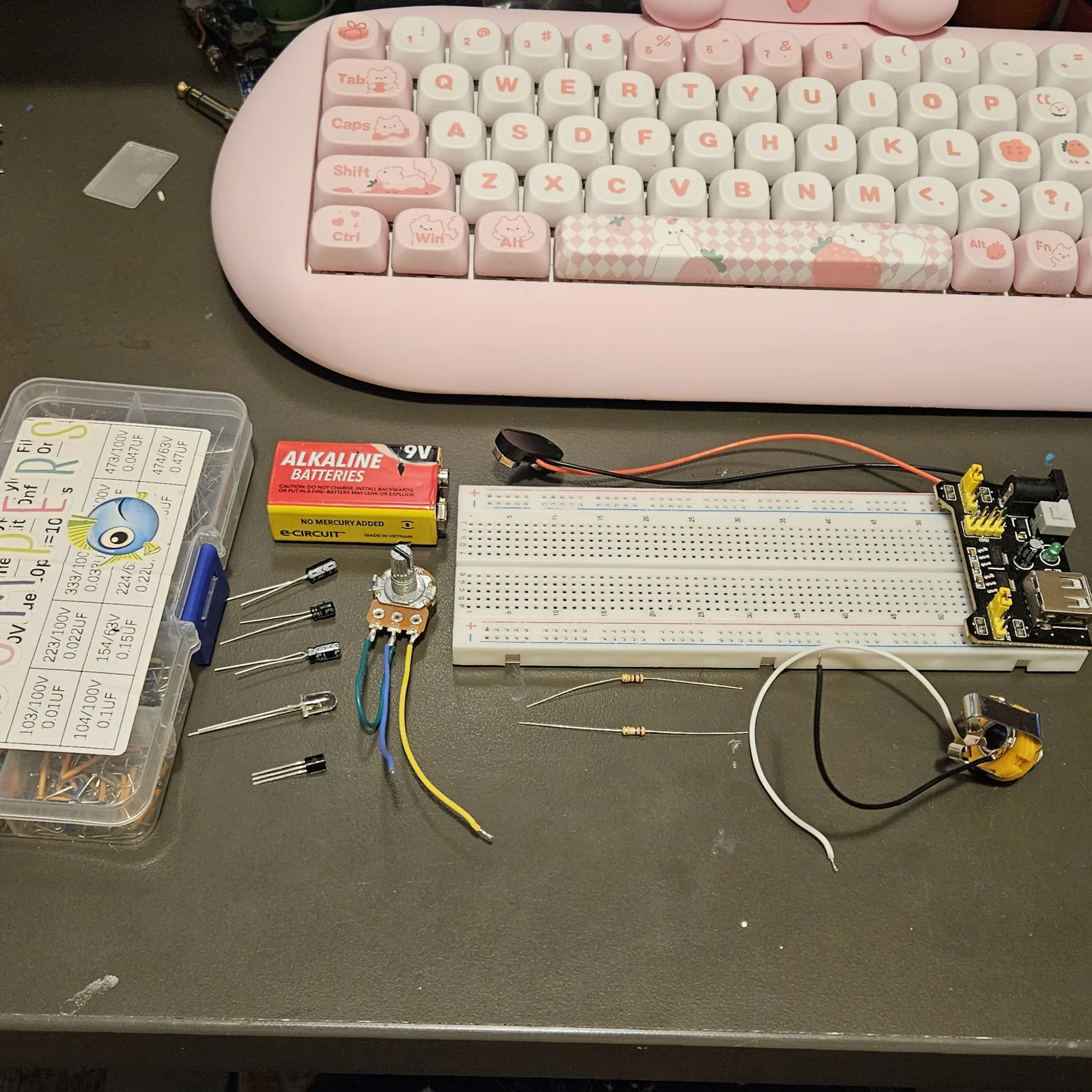
The parts list lives on the build sheet too - this version adds how to spot each part: the printed marking, the package, or the polarity clue.
- 1× 2N3904 NPN transistor, TO-92 - but buy five. The avalanche voltage this circuit leans on is unspecified and varies part to part, and some simply won't oscillate on 12V. Spot it: the little half-cylinder with three legs and one flat face, part number printed on the flat
- 1× 1K resistor - the current limit; sets the fast end of the sweep. Spot it: bands brown-black-red
- 1× 100K resistor - output series resistor. Spot it: bands brown-black-yellow
- 1× 10 µF electrolytic, rated 25V or higher - the timing cap. Spot it: a little can; the stripe marks the minus leg, longer leg is +. Bring a 1 µF and a 100nF too - see the pitch table below
- 1× 5mm LED - the discharge path and your tuning indicator. Any color; the one in the photos has a water-clear lens. Long leg is the anode
- 1× 10K linear pot - the pitch knob. Spot it: marked B10K. Lug 1 and the wiper get tied together at the pot, and it goes to the board on flying leads
- 1× output lead - a jack or croc-clip lead to whatever you are feeding: tip and sleeve
- A breadboard and 4 jumpers - the photos use a full-size board with a plug-on power module at the end, but the build only spans columns 3 to 24, so a half-size board fits it too
- 12–18V DC supply - a bench supply or wall adapter. Four salvaged vape cells in series land at 14.8V nominal, inside the window - but nobody has run this build on a pack yet, so meter it first and call it an experiment
Reading the breadboard
This guide names exact holes, like A11 or D7. Letters run across the board and numbers run along it, and both are printed on the board itself, so every instruction below points at one hole you can put a finger on. The five holes in a bank that share a number are all the same electrical point - A11, B11, C11, D11 and E11 are one node with five ways in.
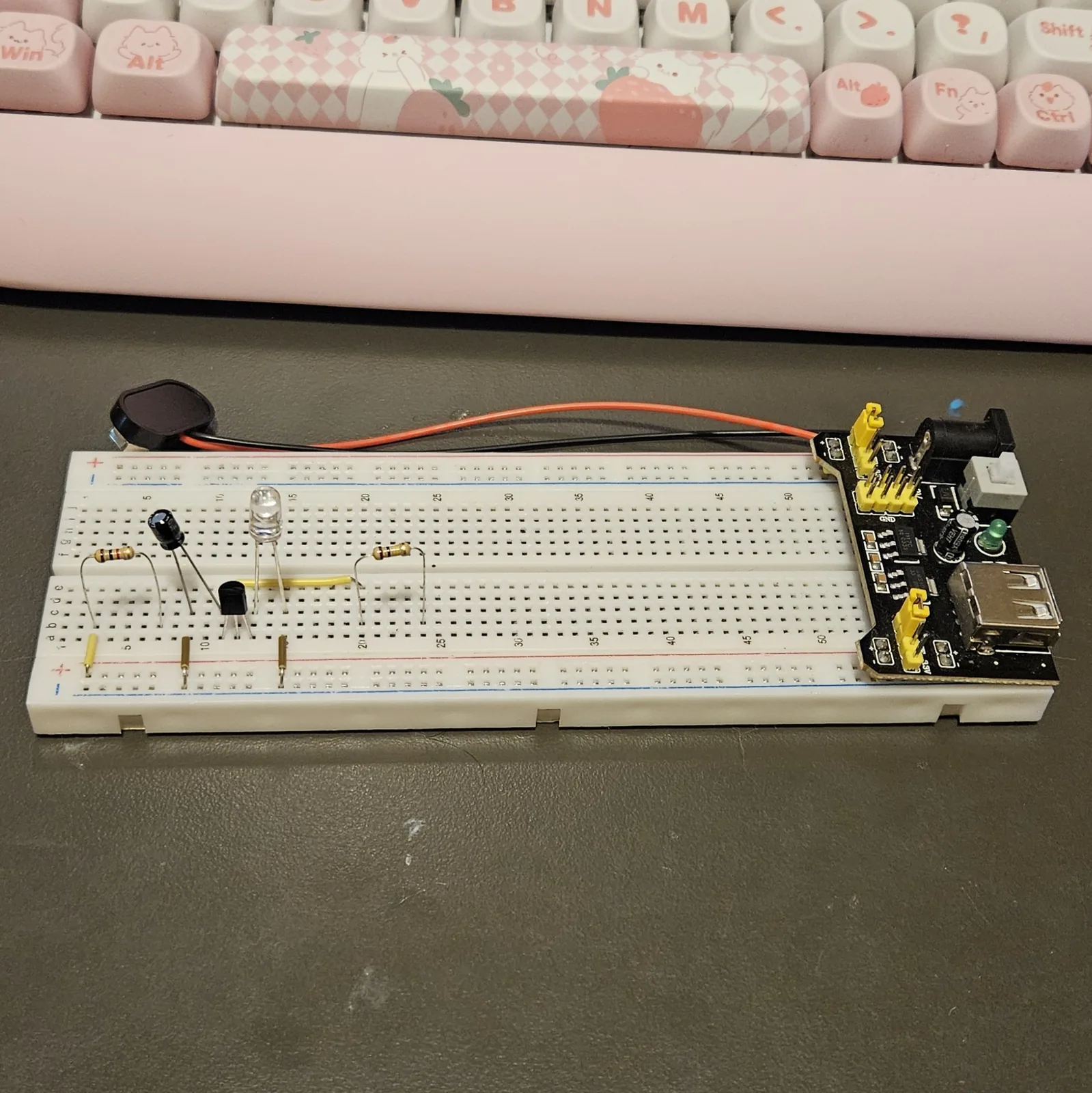
The whole build lives in the A to E bank and the pair of rails beside it - the F to J bank stays empty. On the rails, red stripe is + and blue stripe is −. The black power module visible in the photos is a leftover passenger from another project - it came off before power-up, and its 5V output would be no use to this build anyway. Before you wire anything, meter each rail end to end - plenty of boards break the rails at the midpoint, and if yours does, bridge the break with a jumper.
Quick reference - the whole build on one card
No chip this time - the whole thing hangs off three transistor legs and one rule about an empty column. This is the bench card.
Emitter, base, collector - left to right, flat face toward you. Column 12 holds the base and nothing else. That floating base is the whole oscillator - the moment anything touches column 12 it stops being a negative-resistance switch and starts being a transistor.
Charging side
- Jumper: + rail → A3
- 1K: B3 → B7
- Pot: lug 1 + wiper (tied) → D7, lug 3 → D11
The core
- Q1: E → A11, B → A12, C → A13
- 10µF: + leg C11, − leg C9; jumper A9 → − rail
- Column 12: the base, and nothing else
Out
- Jumper: E11 → E20
- 100K: B20 → B24
- Output tip → D24, sleeve → − rail
LED and power
- LED: anode C13, cathode C15; jumper A15 → − rail
- 12–18V: + → + rail, − → − rail
Steps 1–2 The semiconductors
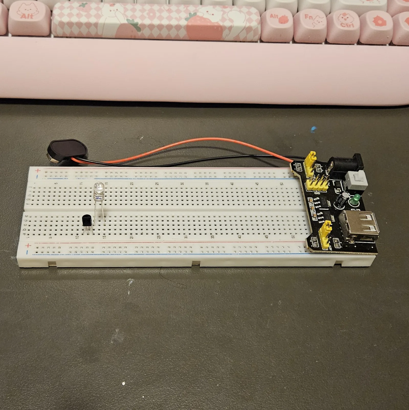
Transistor first, then the LED. Get the three legs the right way around, keep the base column empty, and the rest of this build is pushing parts into holes.
| Step | Do |
|---|---|
| 1 | Hold the transistor with the flat face toward you and the legs pointing down. Left to right the legs are emitter, base, collector. Splay them to a tenth of an inch and push them into A11, A12 and A13 in that order |
| 2 | LED: long leg (anode) into C13, short leg / flat side into C15 |
Column 12 now holds the base and it must never hold anything else. The 2N3904 is in the circuit backwards on purpose: its emitter–base junction is run in reverse avalanche, and with the base floating it behaves as a negative-resistance switch. Load column 12 with anything and it goes back to being a transistor, and the oscillator dies. Every other part in this build stays out of that column.
Steps 3–6 The jumpers
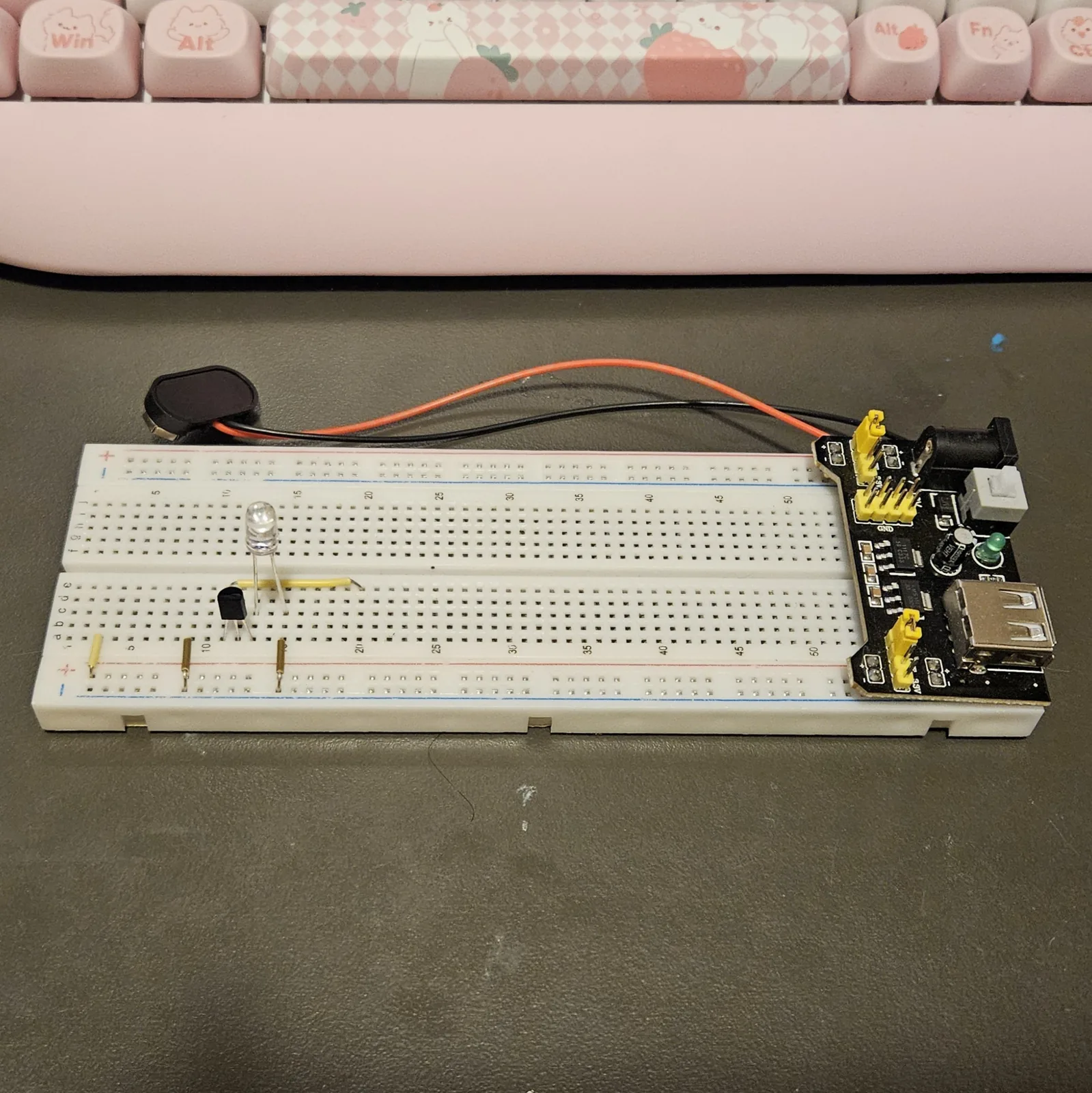
Four of them: power in, two drops to the ground rail, and the bridge that carries the timing node over to the output side.
| Step | Do |
|---|---|
| 3 | Jumper: + rail to A3 |
| 4 | Jumper: A9 to the − rail |
| 5 | Jumper: A15 to the − rail |
| 6 | Jumper: E11 to E20. This is the bridge for the timing node - it runs over the top of columns 12 to 19 without touching them |
Steps 7–8 The resistors
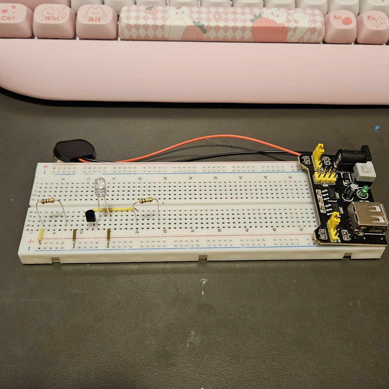
| Step | Do |
|---|---|
| 7 | Resistor 1K (brown-black-red): B3 to B7 |
| 8 | Resistor 100K (brown-black-yellow): B20 to B24 |
Step 9 The electrolytic
| Step | Do |
|---|---|
| 9 | Cap 10 µF: + leg into C11, striped − leg into C9. Two columns apart - spread the legs gently |
Polarity, twice: the cap's stripe goes to ground at column 9, and the LED's long leg went to column 13. Reverse the cap and it will get warm and eventually vent; reverse the LED and the circuit simply sits there doing nothing.
Steps 10–12 Off the board: pot and output
Nothing else goes into the breadboard. The pitch pot and the output lead fly off the board, so this is the part you unplug when you want the board back.
| Step | Do |
|---|---|
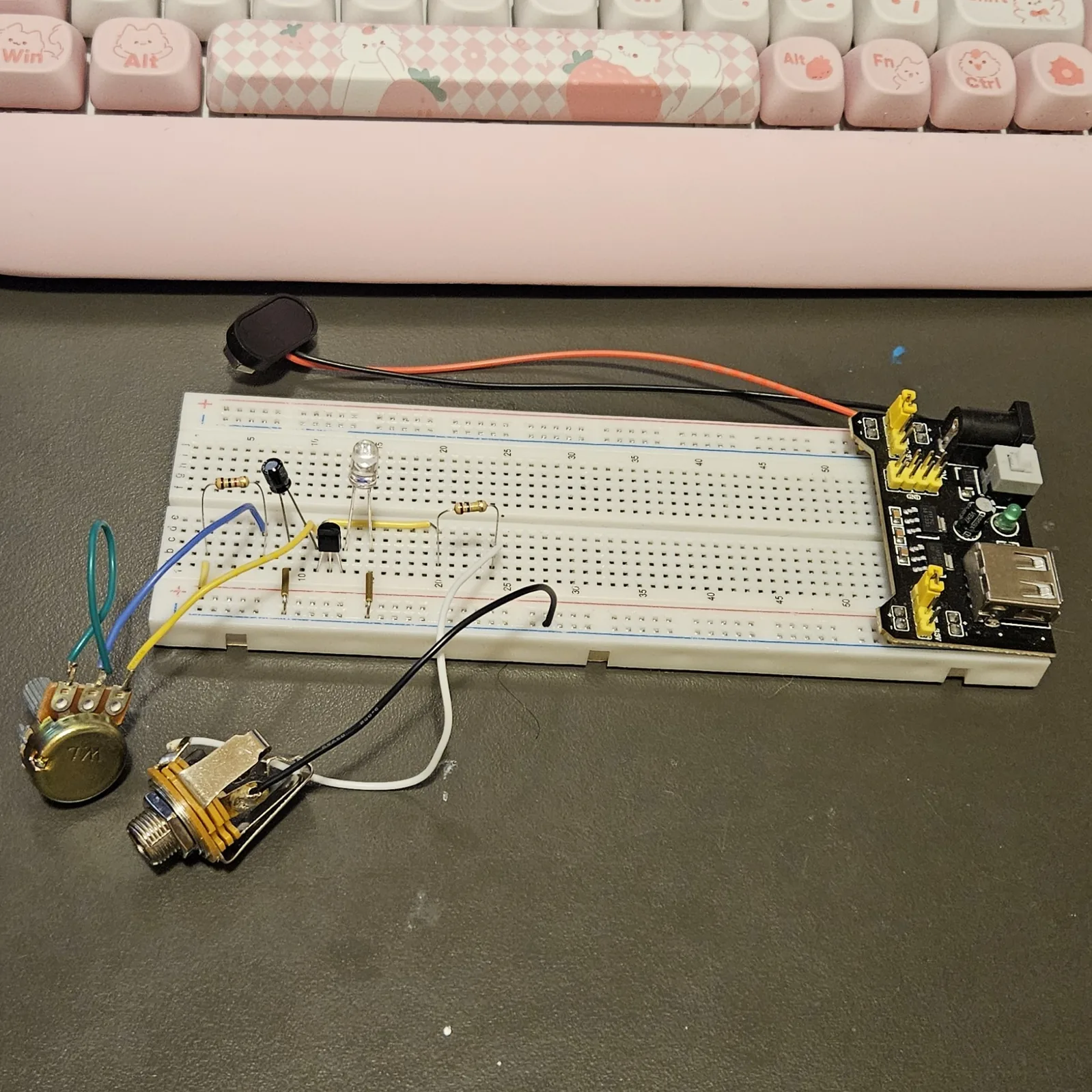
| 10 | Pot flying leads: lug 1 and the wiper, tied together at the pot, into D7; lug 3 into D11 |
| 11 | Output lead: tip into D24 |
| 12 | Output lead: sleeve to the − rail |
Wired this way the pot is a rheostat: 0 to 10K in series with the 1K, so the total charging resistance sweeps 1K to 11K. That is the variable-resistor wiring from the rest of the series, with the 1K playing the same guard role as always - at zero ohms there is still something for the cap to charge through. In the photo the tie is the short green loop soldered between lug 1 and the wiper; the blue lead is the tied pair, and the yellow lead is lug 3.
Steps 13–16 Checks, then power
Two meter checks with the supply still off, then the supply, then the fun part.
| Step | Do |
|---|---|
| 13 | Continuity, supply off: + rail to column 3; column 7 to both pot points; column 11 to column 20; column 12 to nothing at all; columns 9 and 15 each to the − rail |
| 14 | Resistance from the + rail to the − rail: it should read high and roughly steady. A few hundred ohms or less means a short - find it before you power up |
| 15 | Supply set to 12V and switched off: positive to the + rail, negative to the − rail |
| 16 | Power on with the pot at mid-travel. The LED should blink or flutter, speeding up as you sweep the pot |
With the 10µF in, this runs slow enough to watch. A meter on column 11 in DC volts hovers somewhere in the middle of the rail as the cap ramps and dumps; on a scope, column 11 is a sawtooth - a slow charge curve and a near-vertical collapse. 15V gives a livelier, faster oscillator; 18V is the ceiling.
⚠ If it doesn't work
| Symptom | Check |
|---|---|
| Dead. LED off, column 11 sits pinned near V+. | Nothing is discharging the cap. Check the LED direction first, then swap the transistor, then push the supply to 15–18V. This is by far the most common failure and it is usually the transistor. |
| Dead. Column 11 sits near 0V. | The transistor is in backwards (C–B–E), or a leaky part. Pull it, confirm flat face toward you, reseat in 11 / 12 / 13. |
| Oscillates, but only over a sliver of pot travel. | A log pot rather than linear, or lug 1 and the wiper aren't actually tied. Meter lug 1 to wiper - it should read 0 Ω. |
| Rate won't change at all. | Pot leads in the wrong columns, or the wiper is open. Meter lug 3 to the tied pair while turning: it should sweep 0 to 10K. |
| The cap is warm or bulging. | It is in backwards. Power down now and replace it - a reversed electrolytic doesn't recover. |
| Runs, but stops when you touch the board. | Something is loading the base column. Clear column 12, and trim the base leg shorter so it can't lean into a neighbor. |
How it works, in one breath
The supply charges the cap through the 1K and the pot, so the voltage on column 11 ramps slowly upward. The transistor is in backwards, its emitter–base junction sitting across that cap like a dam - and every junction has a voltage where it breaks. When the ramp reaches the 2N3904's avalanche voltage, the junction snaps into conduction all at once, the cap dumps through the transistor and the LED to ground, the LED flashes, and the whole thing starts over. Ramp, snap, flash: a sawtooth. That break voltage is an accident of manufacturing - unspecified, different in every part - which is why some transistors won't go at 12V, why the pitch drifts, and why this thing sounds alive rather than calibrated.
What C1 does to the pitch
Ten times the cap is a tenth the pitch. Raising the supply raises the pitch across the whole range too - roughly double from 12V to 18V.
| C1 | Approx. range on 12V | Character |
|---|---|---|
| 10 µF | 7–77 Hz | Visible blink through to a low rumble. Best value for proving it works. |
| 1 µF | 70–770 Hz | The musical sweep. The LED goes to a steady dim glow. |
| 100nF | 0.7–7.7 kHz | Bright and thin, buzzy at the top. |
| 10nF | 7 kHz + | Runs out of headroom; breadboard stray capacitance starts to matter. |
Things to try
- Find your best transistor. Since nothing is soldered, swap all five 2N3904s through and keep the one that fires cleanest at your supply voltage. Mark it - that one goes on the real board when this build earns a permanent home.
- Block the DC. The output at column 24 rides on a large DC offset - fine into a modular input, not fine into most pedals or an interface. A 1 µF film or electrolytic in series after column 24 sorts it. It is not on the stripboard layout, so decide whether you want it there before you commit to solder.
- Play the supply. The pitch tracks the supply voltage, so a variable bench supply is a second pitch knob - and somewhere below 12V is the exact voltage where your particular transistor gives up, which is worth knowing before you build the keeper.
- Swap the cap. The table above is the whole menu - clip the 10µF out and push in the 1µF for the musical range. Mind the stripe every time.
The Super Simple Oscillator is Sam Battle's circuit - shared free on lookmumnocomputer.com and built by thousands as a first synth voice. This breadboard recipe, the stripboard layout it was translated from, and the words are my own. Build it, bend it, make it yours.