Bug Mixer
Four bugs, one voice, a speaker and a line out · A TL072 on eleven strips · By Onion Madder · Mess O' Pedals
The Bug Bus gives the six boards in the Bug Box one supply. This gives them one voice. Four of them make sound - the Hive, Dragonfly, Cicada and Grub - and each gets a level knob here. They sum in one half of a TL072, and the mix leaves two ways at once: to the Hornet, which drives the speaker, and through a 1K to a line-out jack. Nothing to switch between them. The box plays on its own, and plugs into anything.
What you'll need
tap to expand / collapse
- 1× TL072 dual op-amp, 8-pin DIP - spot it: TL072 on top, notch or dot marks pin 1. An NE5532 or an LM358 sits in the same holes; the LM358 is the safe one if a 9V supply ever proves too little for the TL072
- 4× 100K (brown-black-yellow, R1 to R4) - the summing resistors, one per channel. They stand in a row and reach down to their channel strips; the longest lies across seven holes, so leave its leads long
- 1× 22K (red-red-orange, R5) - the feedback resistor. It sets the gain: 22 over 100 is about a fifth of each channel. Stands up
- 2× 100K (R6, R7) - the half-rail divider. R7 stands up
- 1× 1K (brown-black-red, R8) - on the line out, so a shorted jack cannot hurt the chip. Stands up, across a cut
- 4× 100n ceramic (104, C1 to C4) - one per channel, coupling the pot wiper in. Each lies across the cut in its own strip
- 1× 100n ceramic (104, C8) - across the chip's supply
- 3× 10 µF electrolytic (C5, C6, C7) - the reference hold and the two output couplers. Spot it: stripe marks the negative leg. C5's stripe goes to the ground strip; C6 and C7 have their plus on the chip's output strip, since the mix sits at half the rail
- Stripboard, 11 strips × 22 holes or larger, and solid wire for four links, one of them diagonal
Off the board
- 4× 100K pots, the level knobs - spot it: A100K (log) is the one that feels like a volume knob; B100K works and is just crowded at the top. Wired as dividers: all three lugs used
- 1× 3.5 mm or 1/4″ jack, the line out
- The Hornet and its speaker - the other place the mix goes
- A 9V supply - one of the Bug Bus's filtered outputs is the obvious one
The layout file is the guide
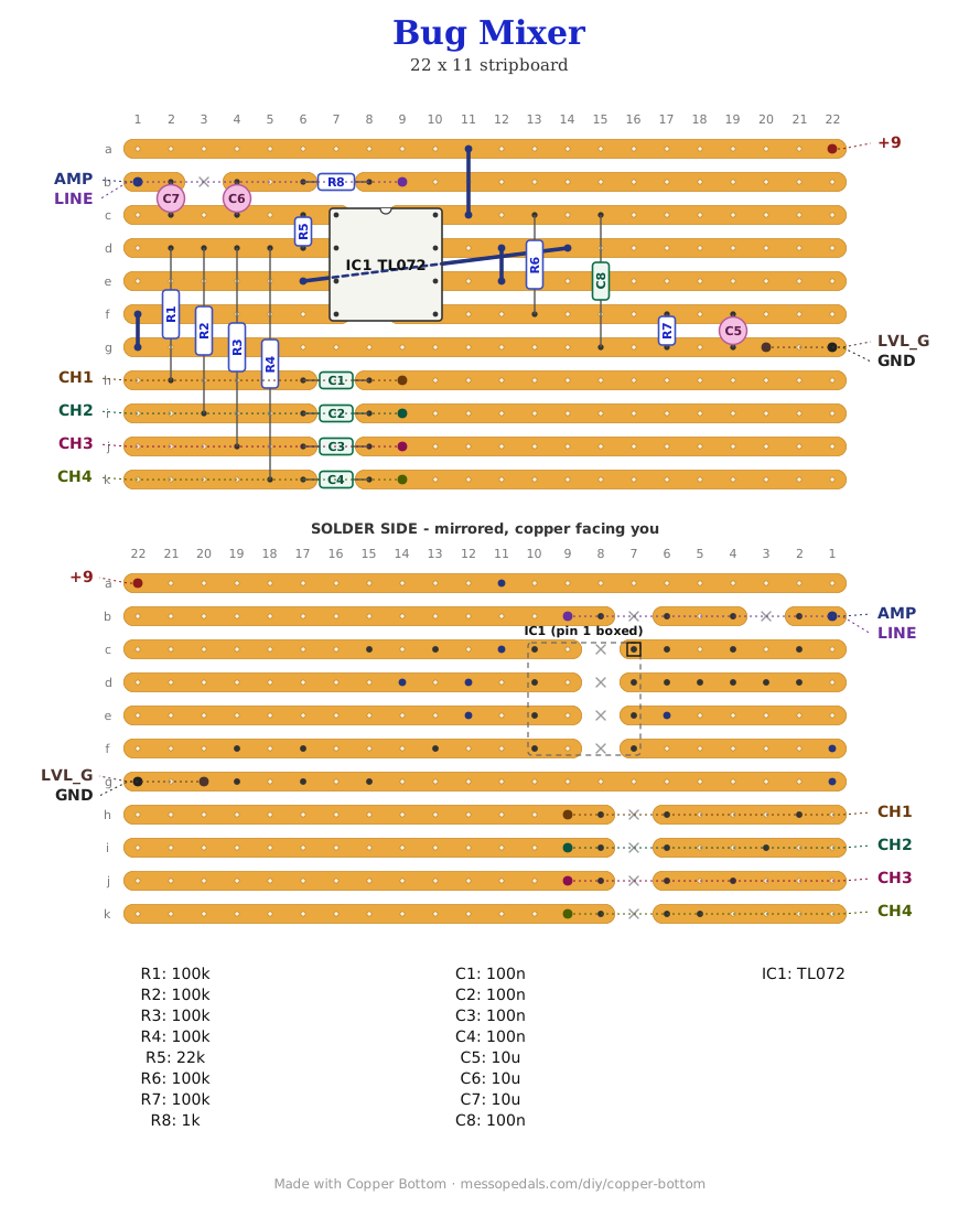
Like the 555 theremin and the Opto Duet, the build document for this one is the file itself: ↓ Download Bug_Mixer.json - import it into Copper Bottom and the editor gives you the board picture, the placement walkthrough, the electrical checks and a printable build sheet, all from the same file. No coordinates are written out on this page on purpose: the editor is the viewer, and a number typed twice is a number that can drift.
One link runs diagonally under the chip. J4 carries the buffered reference from the right-hand half of the op-amp to pin 3 on the left, and there is no strip that goes there. On the copper side it is a wire from one hole to another and does not care about the angle; the editor draws it as the slant it is. Lay it on the solder side, or over the chip with a sleeve on it.
The netlist
Quoted verbatim from the layout file. It was written from the board, so checking the board against it can only pass - what it is for is carrying the circuit somewhere else, and telling you what each strip is supposed to be doing while you stare at it.
The off-board wiring
Nine pads leave the board. Four of them are the level knobs.
| Pad | Goes to |
|---|---|
| +9 / GND | A filtered output of the Bug Bus, and its ground pad. The Hornet is on the bus's unfiltered output; this board is happier on a filtered one |
| CH1 … CH4 | The level pots, wiper each. Lug 1 of each pot is that bug board's audio OUT, wired straight from the board to the pot; lug 3 goes to LVL_G. CH1 is the Hive, CH2 the Dragonfly, CH3 the Cicada, CH4 the Grub - by convention only, they are identical |
| LVL_G | Lug 3 of all four pots. One pad, four wires, or daisy-chain the lugs and run one |
| AMP | The Hornet's input - into its volume pot, lug 1, exactly as if this board were a guitar. The Hornet's volume is now the box's speaker volume |
| LINE | The line-out jack, tip. Sleeve to GND. Through the 1K on the board. It is always live; the speaker does not switch off when a cable goes in unless you use a switched jack here and put its switch contact in the Hornet's speaker lead, the way the Garden Variety does it |
How it works, in one breath
An op-amp mixer is a see-saw. The inverting input, SUM, is held at the reference voltage by feedback, so every channel's 100K sees the same quiet point and pushes its own current into it, and none of them can feel the others - that is the difference between this and four resistors twisted together, where turning one knob changes what the rest do. The feedback resistor decides how much of that summed current becomes output voltage: 22K over 100K is a gain of about 0.22 per channel, so a bug at full swing, nine volts peak to peak, arrives as about two volts, which is a hot line level, and four at full would ask for more than a 9V chip can swing. The pots are how you keep it clean, and clipping a square wave is not a tragedy anyway.
The other half of the chip does nothing but hold a voltage. Two 100Ks split the supply in half, a 10 µF steadies it, and op-amp B follows it - its output tied straight to its inverting input - so the reference has an op-amp behind it instead of a 100K-ish resistor. That is what lets the whole thing run from a single 9V: the mix sits at four and a half volts and swings around it, the input caps keep the boards' DC out, and the output caps keep the four and a half volts in. Pins 6 and 7 tied together is the follower, not a mistake, if the checker mentions it.
Levels, unmeasured. The bug boards put out square waves near the full rail, on a 0V base. Into this board that is fine; the caps take the DC and the 22K takes the size. If the line out is too hot for what it plugs into, the fix is the feedback resistor: 10K gives a tenth per channel and a line out that no pedal input will flinch at.
Things to try
- A fifth channel is one more strip: a pad, a 100n across a cut, and a 100K up to SUM. The chip does not care how many
- Tone. A 10n from SUM to MIX, across the 22K, rolls the top off every square wave at once - one cap, a rounder box. A 47n is a lot rounder
- A master level. Replace R8 with a 10K pot wired as a divider, wiper to the jack: line out gets its own knob and the speaker keeps the Hornet's
- Send a bug out on its own. Any board's OUT can go to a jack of its own before it reaches its level pot. Then the box is four instruments and a mixer, and a patch cable pulls one out
Circuit is the single-supply inverting mixer from every op-amp datasheet's application notes - the same idea as the MFOS mini mixer with the bipolar supply replaced by a buffered half rail. The layout is Onion Madder's, drawn in Copper Bottom for the Bug Box.