Mosquito
The Atari Punk Console on an NE556, soldered down · Ten strips by sixteen holes · By Onion Madder · Mess O' Pedals
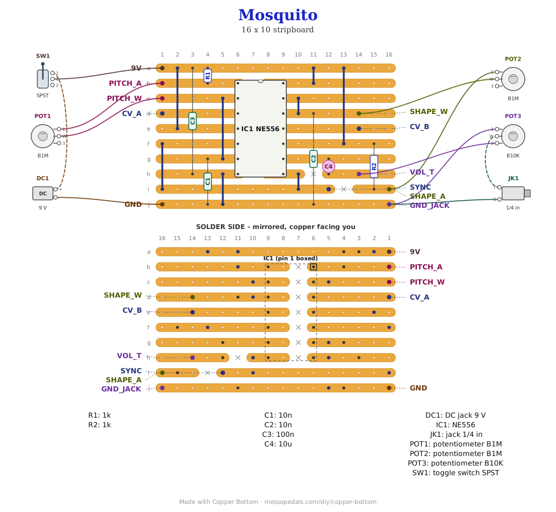
The Dead-Bug Mosquito is the one bug in the series that never got a permanent home - the Hive, Cicada, Grub, Dragonfly and Hornet all made it onto stripboard, and the noise box that started the whole thing did not. This is it: the same NE556, the same two 10n caps and two 1K resistors, the same pitch and shape pots, on ten strips. Timer A runs free, its square wave triggers timer B, and timer B's one-shot is the sound. The output leaves through a 10 µF cap to a volume pot. Nothing added, nothing taken away; the dead-bug page's extras - the CV inputs, the sync out - get an empty pad each, so they can be added without a redraw.
What you'll need
tap to expand / collapse
- 1× NE556 dual timer, 14-pin DIP - spot it: NE556 on top, not 555; a notch or dot marks pin 1. Two 555s in one package, which is the whole trick of the circuit
- 2× 1K (brown-black-red, R1 and R2) - R1 from the supply to pin 1, so the pitch pot at zero cannot short the timer's output to its own timing input; R2 does the same job for the shape pot. R1 stands up
- 2× 10n ceramic (103, C1 and C2) - the timing caps, one per timer. C1 lies from the left of the chip down to the ground strip, C2 from the right
- 1× 100n ceramic (104, C3) - supply decoupling, from the top strip down to the chip's ground pin. A long one; leave its leads long
- 1× 10 µF electrolytic (C4) - the output DC blocker. Spot it: stripe marks the negative leg. Its plus goes on pin 9's strip; it stands up
- Stripboard, 10 strips × 16 holes or larger, and solid wire for eight short links
Off the board
- 2× 1M pots - pitch and shape. Spot it: B1M is the linear one. Wired as variable resistors: the wiper and one outer lug, the third lug left empty. A 500K for shape tightens its range and is fine
- 1× 10K pot, the volume - spot it: B10K. Wired as a divider: all three lugs. Lug 3 to VOL_T, lug 1 to GND_JACK, wiper to the jack
- 1× 1/4″ jack for the output - or a small 8 Ω speaker straight off the volume wiper, the way the dead-bug build plays
- 1× SPST toggle for power, in the positive leg between the DC jack and the 9V pad
- 1× DC jack or 9V battery snap - a 9V battery, or at least two vape cells in series
- An upright 125B - the drill template further down
The layout file is the guide
Like the 555 theremin and the Opto Duet, the build document for this one is the file itself: ↓ Download Mosquito.json - import it into Copper Bottom and the editor gives you the board picture, the placement walkthrough, the electrical checks and a printable build sheet, all from the same file. No coordinates are written out on this page on purpose: the editor is the viewer, and a number typed twice is a number that can drift.
Strip i is the trigger bus. Timer A's output leaves pin 5 on the left of the chip and timer B's trigger is pin 8 on the right, and no single strip joins them - so a link takes OUT A down to strip i, the strip runs under the chip, and a second link brings it up to pin 8. The SYNC pad sits on that strip: it is the raw oscillator square, the clock out the dead-bug page describes, through a 1K if you use it. Two cuts on the right end of strips h and i make room for the volume and shape pads.
The netlist
Quoted verbatim from the layout file. It was written from the board, so checking the board against it can only pass - what it is for is carrying the circuit somewhere else, and telling you what each strip is supposed to be doing while you stare at it.
The off-board wiring
Eleven pads leave the board. Three of them are for extras and stay empty on the base build.
| Pad | Goes to |
|---|---|
| 9V / GND | The supply. 9V through the power toggle from the DC jack or battery snap; GND to the jack's sleeve or the snap's black lead |
| PITCH_A / PITCH_W | The pitch pot, as a variable resistor: one outer lug to PITCH_A, the wiper to PITCH_W, the third lug empty. Which outer lug decides which way the knob turns; swap them if it feels backwards |
| SHAPE_A / SHAPE_W | The shape pot, the same way: one outer lug to SHAPE_A, the wiper to SHAPE_W, the third lug empty |
| VOL_T | The volume pot, lug 3 - the top of the divider. The output arrives here through C4 |
| GND_JACK | The volume pot's lug 1 and the output jack's sleeve. The wiper goes straight to the jack tip and never touches the board |
| CV_A / CV_B | Empty. Pins 3 and 11, the control-voltage inputs. The dead-bug page's CV mod is a 100K from a jack tip to one of these; a 10n from either to ground is the other thing they are sometimes given |
| SYNC | Empty. Timer A's raw square at the pitch rate - a 1K to a jack tip makes it the clock out the dead-bug page describes |
↓ Same box, jacks on top (PDF)
The second sheet keeps every control where this one has it and moves the jacks - power and audio - to the top wall, so the cables leave upward. Two ways to drill one box; pick one.
Drawn for the layout file's parts and nothing else: pitch, shape and volume down the left, the power toggle on the right, DC and the output jack along the bottom. Nobody has drilled this one yet.
Print at 100% / “Actual size”, never “Fit to page” - check the bar measures exactly 4″ before you touch a drill. The face is 66 by 121 mm but only 42 mm of it is drillable once the lid lip is clear, which is why everything sits in a column.
How it works, in one breath
Two timers, one chasing the other. Timer A is an astable: R1 and the pitch pot charge C1 toward two thirds of the supply, the timer flips and discharges it back to a third, and round it goes at a rate the pitch pot sets - a square wave on pin 5. That square goes down the bus strip to pin 8, timer B's trigger. Timer B is a monostable: every time the trigger falls it puts out one pulse whose width is R2 plus the shape pot charging C2, and then it waits for the next fall. When the pulse is shorter than the pitch period you hear the pitch; when it is longer, timer B misses triggers and you hear the divisions and the beating between them, which is the Atari Punk Console's whole personality. C4 takes the DC off pin 9 and the volume pot hands what is left to the jack.
The 1Ks are not optional. With a pot from a timer's discharge pin to its threshold, zero ohms would tie the output straight to the timing cap and the timer would stop. R1 and R2 are the floor under the knob, which is why each pot is wired as a two-lug variable resistor and not a divider - the same rule every pitch pot on this site follows.
Things to try
- CV in. A 100K from a jack tip to CV_A bends the pitch with a voltage; the same into CV_B bends the shape. Sleeve to ground. The dead-bug page has the whole mod
- Sync out. A 1K from SYNC to a jack tip is timer A's clock, to run the Grub or the Firefly off this box
- A second one-shot. The dead-bug page's NE555 voice 2 hangs off the same trigger; SYNC is that node, so it wires up from the pad
- Bigger timing caps (47n, 100n) push both timers down into clicks and rhythms; smaller ones (1n) push them up into whistles
Circuit is Forrest Mims's Stepped Tone Generator, the Atari Punk Console, as the Dead-Bug Mosquito builds it. The layout is Onion Madder's, drawn in Copper Bottom.